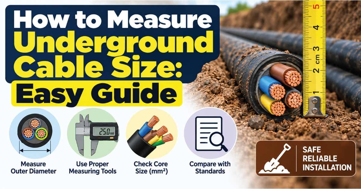
Measuring underground cable size correctly is essential for safe electrical distribution, reliable equipment operation, and acceptable voltage drop. Unlike a cable installed in open air, an underground cable operates within soil, ducts, conduits, trenches, or other enclosed conditions that can affect heat dissipation and current-carrying capacity.
To measure underground cable size, you need to identify the conductor size, determine the cable length, calculate the expected load current, consider voltage drop, and account for the installation method. Simply measuring the outside diameter of an underground cable is not enough because insulation, sheathing, armor, and multiple conductors can significantly increase its overall diameter.
This guide explains how to measure underground cable size, how to identify conductor area, how AWG and mm² sizes relate, how cable length affects sizing, and what to check before selecting a replacement or new underground cable.
What Is Underground Cable Size?
Underground cable size generally refers to the cross-sectional area of the conductor inside the cable. It is commonly expressed in square millimeters (mm²) or AWG (American Wire Gauge), depending on the region and cable system.
The conductor size affects important electrical characteristics such as:
- Current-carrying capacity
- Electrical resistance
- Voltage drop
- Heat generation
- Maximum practical circuit length
- Connection and termination requirements
An underground cable may contain one or several insulated conductors. It can also include a metallic screen, armor, sheath, or protective layers.
This means the overall cable diameter is not the same as conductor size.
For example, a multicore underground power cable may have a relatively large outside diameter while each individual conductor has a much smaller cross-sectional area. Correct measurement therefore requires identifying the conductor rather than relying only on the cable’s external dimensions.
Why Correct Underground Cable Sizing Matters
The correct cable size helps ensure that the electrical system can carry its intended load without excessive heating or voltage loss.
An undersized cable has greater resistance and may experience excessive voltage drop and heating. An oversized cable can be electrically suitable but may unnecessarily increase material costs, installation difficulty, bending requirements, and termination size.
Proper underground cable sizing considers:
- Load current
- Cable length
- System voltage
- Voltage-drop requirements
- Installation method
- Soil and ambient conditions
- Cable construction
- Number of loaded conductors
- Insulation temperature rating
- Applicable electrical codes and standards
The installation environment is particularly important underground because heat dissipation differs from an exposed cable installation. A cable installed directly in soil may have different thermal conditions from one installed inside a conduit or duct.
Tools Needed to Measure Underground Cable Size
The tools you need depend on whether you are identifying an existing cable or designing a new underground installation.
Useful tools include:
- Digital caliper
- Wire gauge
- Tape measure
- Cable manufacturer’s datasheet
- Cable marking information
- Multimeter for appropriate electrical checks
- Current measurement equipment where suitable
- Voltage-drop calculator or calculation method
- Installation drawings or cable schedules
The safest and easiest method is often to read the manufacturer’s cable marking. Cable markings may identify conductor size, conductor count, voltage rating, insulation type, and other construction details.
If the cable is energized or buried, do not dig up, strip, cut, or disconnect it simply to measure its size. Underground electrical systems can present serious shock and arc-flash hazards. Identification should be performed using documentation, markings, drawings, or appropriate professional testing procedures whenever possible.
How to Measure Underground Cable Size Step by Step
The following process can be used to identify an underground cable and determine whether its size is suitable for an application.
Step 1: Check the Cable Marking
Start by looking for markings on an accessible section of the cable.
Depending on the cable type, markings may identify:
- Conductor size
- AWG or mm² designation
- Number of conductors
- Voltage rating
- Insulation material
- Temperature rating
- Manufacturer
- Cable type
- Applicable certification or standard
If the cable marking provides the conductor size, there is usually no reason to physically measure the conductor.
Step 2: Identify the Number of Conductors
Determine how many conductors are contained within the cable.
A cable may contain:
- Single conductor
- Two conductors
- Three conductors
- Four conductors
- Multiple conductors
Do not confuse the number of conductors with cable size. A four-core cable with 16 mm² conductors is very different electrically from a four-core cable with 2.5 mm² conductors.
Step 3: Identify the Conductor Material
Determine whether the conductor is copper, aluminum, or another specified material.
Copper and aluminum have different electrical resistance and physical characteristics. Therefore, a copper conductor and aluminum conductor with the same cross-sectional area should not automatically be assumed to have identical electrical performance in every application.
Always use the manufacturer’s resistance and ampacity data when available.
Step 4: Measure the Conductor
If the conductor is safely accessible and disconnected, remove enough insulation to expose the conductor.
Use a digital caliper to measure the conductor.
For a solid circular conductor, its approximate cross-sectional area can be calculated using:
A = π × d² ÷ 4
Where:
- A = conductor area
- d = conductor diameter
- π = approximately 3.1416
For example, a solid conductor measuring 4 mm in diameter has an approximate area of:
A = 3.1416 × 4² ÷ 4
A ≈ 12.57 mm²
However, stranded conductors should not be identified simply by measuring the outside diameter of the strand bundle. The most reliable identification method is normally the manufacturer’s marking, cable datasheet, or an appropriate wire gauge.
Underground Cable Size in mm² and AWG
Underground cables may use metric conductor sizes or AWG designations. The two systems should not be treated as exact one-to-one equivalents.
The following table shows approximate conductor areas for commonly encountered AWG sizes.
| AWG Size | Approx. Conductor Area (mm²) | Relative Size |
|---|---|---|
| 18 | 0.82 | Small |
| 16 | 1.31 | Small |
| 14 | 2.08 | Small |
| 12 | 3.31 | Medium |
| 10 | 5.26 | Medium |
| 8 | 8.37 | Medium-large |
| 6 | 13.3 | Large |
| 4 | 21.1 | Large |
| 2 | 33.6 | Very large |
| 1/0 | 53.5 | Very large |
| 2/0 | 67.4 | Extra large |
| 3/0 | 85.0 | Extra large |
| 4/0 | 107 | Extra large |
These are approximate conductor areas and should not be interpreted as universal current ratings.
The permissible current for an underground cable depends on factors such as conductor material, insulation, installation method, soil thermal properties, ambient temperature, grouping, and applicable electrical requirements.
How to Measure Underground Cable Diameter
Sometimes the user is actually trying to determine the physical diameter of an underground cable rather than its electrical conductor size.
These are two different measurements.
Conductor Diameter
This is the diameter of the electrical conductor itself.
Overall Cable Diameter
This is the outside diameter of the complete cable, including:
- Conductor insulation
- Inner sheath
- Filler material
- Metallic screen
- Armor
- Outer jacket or sheath
For cable installation, overall diameter can be important because it affects:
- Conduit selection
- Duct sizing
- Cable pulling
- Bending radius
- Gland selection
- Cable tray capacity
For electrical sizing, however, the conductor’s cross-sectional area is the more important measurement.
If the cable is already buried and its overall diameter cannot be measured directly, the manufacturer’s datasheet is usually the best source.
Measure Underground Cable Length Correctly
Cable length has a major effect on voltage drop.
For a DC two-wire circuit, current normally travels from the source to the load and returns through another conductor. Therefore, the voltage-drop calculation needs to account for the complete electrical path.
For example:
- One-way distance = 50 m
- Positive conductor = 50 m
- Negative conductor = 50 m
- Approximate circuit length = 100 m
For multi-phase systems, the appropriate voltage-drop calculation depends on the system configuration and electrical design.
Do not estimate underground cable length simply by measuring the straight-line distance between two points. The actual route may include:
- Trenches
- Ducts
- Vertical sections
- Service loops
- Equipment entrances
- Bends
- Junction points
- Additional routing around obstacles
A small amount of additional cable length may not matter for a short circuit, but it can become significant on long underground runs.
Determine the Current Before Choosing Cable Size
Once cable length is known, determine how much current the circuit must carry.
The best source is the equipment manufacturer’s documentation.
For electrical loads where power and voltage are known, a basic single-phase relationship is:
Current = Power ÷ Voltage
For example, a 2,400 W load operating at 240 V would theoretically draw:
2,400 ÷ 240 = 10 A
Actual circuit design can be more complicated when power factor, motor starting current, efficiency, continuous loading, or other characteristics apply.
For motors, pumps, compressors, and other equipment with starting currents, use the manufacturer’s electrical data rather than sizing the cable from running current alone.
Understand Voltage Drop in Underground Cables
Voltage drop is especially important for long underground cable runs.
As current passes through a conductor, the conductor’s resistance causes some voltage to be lost.
The basic relationship is:
V = I × R
Where:
- V = voltage drop
- I = current
- R = resistance
Cable resistance depends on conductor material, conductor area, temperature, and length.
A useful general relationship is:
Longer cable + higher current + smaller conductor = greater voltage drop
Increasing conductor size reduces resistance, which can reduce voltage drop.
For long underground installations, voltage drop may become the controlling factor in cable selection even when the conductor’s thermal current capacity appears sufficient.
Underground Cable Sizing Example
Consider a hypothetical underground 230 V single-phase circuit supplying a 3,000 W load.
Assume:
- Voltage = 230 V
- Load power = 3,000 W
- One-way cable distance = 80 m
The approximate operating current is:
3,000 ÷ 230 ≈ 13.0 A
The next step is not simply to select a cable based on 13 A.
You would also need to consider:
- Complete circuit length.
- Acceptable voltage drop.
- Conductor material.
- Installation method.
- Soil thermal conditions.
- Cable insulation rating.
- Number of loaded conductors.
- Applicable electrical code.
- Protective device requirements.
- Manufacturer’s specifications.
A cable that is thermally capable of carrying the current may still require a larger conductor if voltage drop becomes excessive over the long run.
This is why underground cable size cannot be selected from amperage alone.
Direct-Buried Cable vs. Underground Conduit
The installation method can affect cable sizing.
Direct-Buried Cable
A cable may be installed directly underground when its construction and the applicable electrical requirements permit it.
Important considerations can include:
- Soil conditions
- Burial depth
- Mechanical protection
- Moisture exposure
- Thermal dissipation
- Cable construction
- Local code requirements
Cable in Conduit or Duct
A cable installed in conduit may experience different heat-transfer conditions.
The conduit material, number of cables, spacing, ambient soil temperature, and installation arrangement can influence allowable loading.
Therefore, you should not automatically assume that the same cable has the same allowable current in every underground installation.
Copper vs. Aluminum Underground Cable
Copper and aluminum are both used for electrical conductors, but their properties differ.
| Characteristic | Copper | Aluminum |
|---|---|---|
| Electrical conductivity | Higher | Lower |
| Typical conductor size for equivalent resistance | Smaller | Larger |
| Weight | Higher for equivalent volume | Lower |
| Connection considerations | Standard practices apply | Requires appropriate terminals and installation practices |
| Cost considerations | Often higher material cost | Often lower material cost |
| Thermal expansion | Lower | Higher |
The appropriate conductor material depends on the application, cable design, installation requirements, and project economics.
Do not replace a copper cable with aluminum solely because the nominal conductor area appears similar. Electrical resistance, termination compatibility, and applicable requirements must be evaluated.
Important Factors When Selecting Underground Cable
Measuring the cable is only the first stage. Before selecting a cable, consider the complete installation.
Current Capacity
The cable must safely carry the expected load under the actual installation conditions.
Voltage Drop
Long runs may require a larger conductor to maintain acceptable voltage at the load.
Cable Length
Longer circuits generally have greater resistance.
Installation Method
Direct burial, conduit, duct, and other installation methods may have different requirements.
Soil Conditions
Soil thermal characteristics can affect heat dissipation and allowable cable loading.
Cable Construction
Insulation, sheath, armor, and conductor material must be suitable for the environment.
Mechanical Protection
Underground cables may need protection against digging, crushing, impact, or other mechanical hazards.
Electrical Protection
Circuit protection must be appropriately coordinated with the cable and electrical system.
Applicable Standards
Electrical installation requirements vary by country, voltage system, cable type, and application. Always follow the applicable local regulations and standards.
Common Underground Cable Measurement Mistakes
Avoid these common errors when identifying or sizing underground cables.
Mistake 1: Measuring the Outside Diameter
Overall diameter does not directly tell you conductor cross-sectional area.
Mistake 2: Ignoring Cable Length
A short cable and a 200-meter cable carrying the same current can have very different voltage-drop requirements.
Mistake 3: Using Only Ampacity
Current capacity alone does not guarantee acceptable voltage drop.
Mistake 4: Forgetting Installation Conditions
Underground thermal conditions can differ substantially from exposed installations.
Mistake 5: Assuming AWG and mm² Are Exact Equivalents
They are different sizing systems. Use manufacturer data for precise identification.
Mistake 6: Measuring a Buried Cable Unsafely
Do not excavate or cut an unknown underground cable without confirming its status and using safe procedures.
Mistake 7: Copying the Existing Cable Size
An existing installation is not necessarily correctly sized. Replacement cable should be evaluated based on the actual load and installation requirements.
Quick Underground Cable Measurement Checklist
Before selecting or replacing an underground cable, record these details:
- Cable conductor size
- AWG or mm² designation
- Conductor material
- Number of conductors
- System voltage
- Load current
- Cable length
- Installation method
- Burial or duct arrangement
- Ambient and soil conditions
- Voltage-drop requirement
- Insulation rating
- Mechanical protection
- Circuit protection
- Applicable local electrical requirements
- Manufacturer’s specifications
Having this information makes it much easier to determine whether an existing cable is suitable or whether a larger conductor is needed.
How to Identify an Unknown Underground Cable
If you do not know the cable size, avoid guessing based on appearance.
Start with documentation:
- Electrical drawings
- Installation records
- Cable schedules
- Equipment manuals
- Manufacturer information
- Cable markings at accessible ends
- Previous inspection records
If documentation is unavailable, a qualified electrician or electrical engineer may be able to identify the cable using appropriate inspection and testing methods.
For buried electrical cables, safety should take priority over physical measurement. Underground utility and power cables may remain energized even when their purpose is unknown.
Never assume an unmarked buried cable is inactive.
When Should You Use a Larger Underground Cable?
A larger conductor may be necessary when:
- The cable run is long.
- Load current is high.
- Voltage drop exceeds the permitted value.
- Installation conditions reduce allowable current capacity.
- Several cables are installed together.
- Ambient or soil temperatures are unfavorable.
- The equipment manufacturer specifies a larger conductor.
- Future load requirements have been deliberately included.
However, oversized cable is not automatically the best choice.
A significantly larger cable can require:
- Larger cable glands
- Larger terminals
- Larger ducts
- More installation space
- Greater pulling force
- Higher material costs
The objective is to select a conductor that satisfies the electrical and installation requirements rather than simply choosing the largest available size.
Frequently Asked Questions About Underground Cable Size
How do I measure underground cable size?
Start by checking the cable markings or installation documentation for the conductor’s AWG or mm² size. If the conductor is safely accessible and isolated, measure the conductor rather than the complete cable. For buried cables, use documentation or qualified inspection methods instead of cutting or excavating an unknown energized cable.
Is underground cable size measured by diameter?
Electrical cable size is normally specified by conductor cross-sectional area, such as mm², or by AWG in some markets. The overall cable diameter includes insulation, sheath, armor, and other materials, so it should not be used as the sole indicator of conductor size.
How does underground cable length affect cable size?
Longer cable runs increase electrical resistance and voltage drop. This can mean that a larger conductor is required even when the load current remains unchanged. Always evaluate the complete circuit length and the applicable voltage-drop requirement when sizing a long underground cable.
Can I measure an underground cable without digging it up?
Yes, if cable markings, drawings, installation records, or manufacturer documentation are available. Physical measurement is generally unnecessary when the cable specification can be identified another way. Never excavate, cut, or disconnect an unknown underground cable without appropriate safety procedures and professional knowledge.
Does underground installation affect cable ampacity?
Yes. The allowable current of a cable can depend on installation conditions such as direct burial, conduit or duct installation, soil thermal properties, ambient temperature, cable grouping, and conductor characteristics. Use the applicable cable-sizing tables, electrical code, and manufacturer’s data for the actual installation.
Final Tips for Measuring Underground Cable Size
Accurate underground cable measurement begins with identifying the conductor size, but proper selection requires much more than measuring diameter.
Keep these points in mind:
- Check cable markings before physically measuring anything.
- Identify the conductor material.
- Use mm² or AWG specifications rather than guessing from appearance.
- Do not confuse overall cable diameter with conductor area.
- Measure the complete electrical route.
- Determine actual load current.
- Evaluate voltage drop for long runs.
- Consider direct burial versus conduit or duct installation.
- Account for soil and thermal conditions.
- Verify cable insulation and construction.
- Select suitable circuit protection.
- Follow applicable local electrical regulations.
- Use manufacturer data whenever exact specifications are required.
For critical, high-voltage, high-current, or long-distance underground installations, cable selection should be verified by a qualified electrical professional using the applicable standards and project-specific calculations.
Conclusion
Knowing how to measure underground cable size involves more than measuring the outside of a buried cable. The most reliable process starts by identifying the conductor size through cable markings or manufacturer documentation. From there, evaluate conductor material, current, cable length, voltage drop, installation method, thermal conditions, and applicable electrical requirements.
For an existing installation, do not assume that the current cable size is correct simply because it has been working. For a new installation, calculate the requirements before selecting the cable.
The correct underground cable is one that safely carries the required current, maintains acceptable voltage at the load, withstands the installation environment, and meets the relevant electrical requirements.