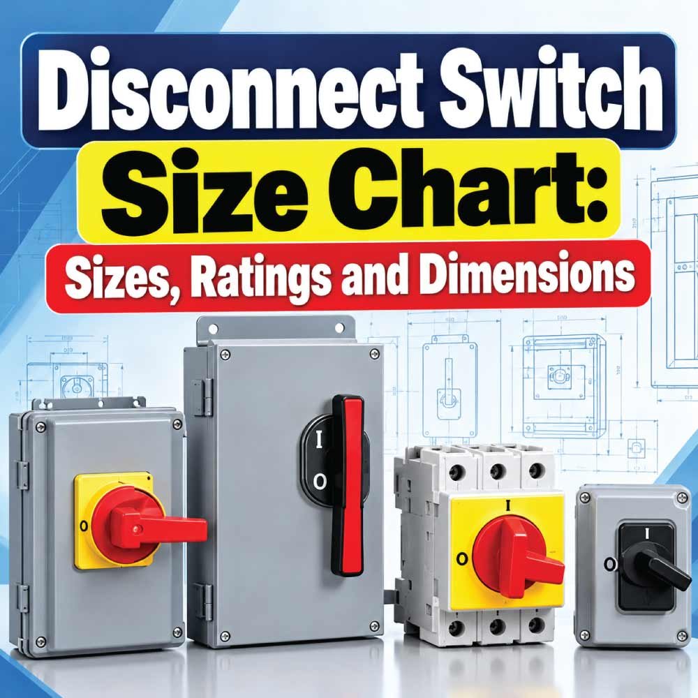
Choosing the correct disconnect switch involves more than matching an amp rating. The switch must also suit the circuit voltage, number of poles, enclosure environment, fuse arrangement, available mounting space, conductor size, and equipment load. A disconnect switch size chart makes it easier to compare common ratings and understand how physical dimensions can change as current capacity increases.
This guide covers common disconnect switch sizes, ampere ratings, dimensions, voltage considerations, fusible and non-fusible options, enclosure types, horsepower ratings, and practical selection factors. Because physical dimensions vary significantly by manufacturer and product family, the dimensions shown should be treated as examples rather than universal industry dimensions.
What Is a Disconnect Switch?
A disconnect switch is a switching device used to disconnect electrical power from a circuit, piece of equipment, motor, or electrical installation. It provides a deliberate means of switching a circuit off and, depending on its design and application, can support maintenance and lockout/tagout procedures.
Disconnect switches are available in several configurations. Common options include fusible disconnect switches, non-fusible disconnect switches, safety switches, enclosed motor disconnects, and specialized switches for demanding environments.
The correct switch is determined by more than amperage. Important characteristics include:
- Current or ampere rating
- Voltage rating
- Number of poles
- AC or DC application
- Fusible or non-fusible design
- Enclosure type
- Horsepower rating where applicable
- Short-circuit or interrupting rating
- Conductor and terminal requirements
- Physical dimensions and mounting arrangement
A switch that physically fits a panel is not necessarily electrically suitable for the circuit.
Disconnect Switch Size Chart
The following chart shows commonly encountered disconnect switch current ratings. These are useful reference points for initial selection, but actual availability depends on the manufacturer and product series.
| Disconnect Switch Rating | Typical Application | Common Configuration | General Size Category |
|---|---|---|---|
| 30 A | Small equipment, motors, branch circuits | 1–3 pole | Small |
| 60 A | Equipment and motor circuits | 2–3 pole | Small |
| 100 A | Larger equipment and feeders | 2–3 pole | Medium |
| 200 A | Large equipment and distribution | 2–3 pole | Medium/Large |
| 400 A | Heavy commercial and industrial loads | Multi-pole | Large |
| 600 A | Large industrial equipment | Multi-pole | Large |
| 800 A | High-current industrial distribution | Multi-pole | Very large |
| 1200 A | Major industrial distribution | Multi-pole | Very large |
There is no single universal physical size for a 30 A, 100 A, or 200 A disconnect. Two switches with the same ampere rating can have different enclosure dimensions because of differences in design, voltage, fuse class, pole arrangement, enclosure rating, terminals, and operating mechanism.
For example, manufacturer product lines commonly extend from 30 A through several hundred amperes, with some safety-switch families available up to 600 A or more.
Common Disconnect Switch Amp Ratings
30 Amp Disconnect Switch
A 30 A disconnect is one of the common smaller sizes used for equipment and motor applications. Depending on the design, it may be available as a fusible or non-fusible switch.
A 30 A rating does not mean the switch can automatically be used on every 30 A circuit. The voltage, conductor requirements, load characteristics, enclosure, and applicable electrical requirements must also match.
Some manufacturer examples show 30 A switches available in one-, two-, and three-pole configurations.
60 Amp Disconnect Switch
A 60 A disconnect is commonly used when a circuit requires more current capacity than a 30 A device. It is frequently encountered in motor and equipment applications.
Physical dimensions may remain similar between certain 30 A and 60 A product families. Eaton, for example, lists some 30 A and 60 A switch designs with the same external dimensions, demonstrating why amp rating alone cannot be used to predict enclosure size.
100 Amp Disconnect Switch
A 100 A disconnect generally requires more substantial terminals and internal current-carrying components than smaller switches. It may be used for larger equipment, motors, feeders, and other applications depending on the product rating.
The enclosure may also become larger because additional wire-bending space and larger conductor terminals can be required.
200 Amp Disconnect Switch
A 200 A disconnect is commonly associated with larger equipment and distribution applications. At this size, conductor routing, terminal space, enclosure depth, and mounting requirements become particularly important.
A 200 A switch should never be selected solely by looking at the number stamped on the existing breaker. The entire electrical application must be evaluated.
Disconnect Switch Dimensions
Disconnect switch dimensions normally include more than simple height and width. When comparing products, look at:
- Overall height
- Overall width
- Overall depth
- Mounting-hole spacing
- Mounting depth
- Handle or operating mechanism clearance
- Wire-bending space
- Terminal or lug space
- Door clearance
- Conduit-entry locations
The following example illustrates how dimensions can vary by amp rating within one manufacturer’s product family.
| Rating | Example Length | Example Width | Example Depth |
|---|---|---|---|
| 30 A | 7-5/16 in | 4-15/32 in | 4-11/32 in |
| 60 A | 7-5/16 in | 4-15/32 in | 4-11/32 in |
| 100 A | 9-27/32 in | 5-11/32 in | 4-27/32 in |
| 200 A | 12-3/16 in | 7-7/32 in | 4-27/32 in |
These measurements are an example from a specific disconnect product family and should not be treated as universal dimensions. Manufacturer catalogs can use different enclosure designs, terminal arrangements, and dimensional references.
Why Disconnect Dimensions Vary
Ampere Rating
Higher-current switches often require larger terminals, conductors, internal components, and wire-bending areas. This can increase the overall enclosure size.
However, the relationship is not always linear. Two ratings may use the same enclosure in one product series while requiring completely different enclosures in another.
Fuse Arrangement
Fusible switches generally need space for fuse holders or clips. As a result, a fusible version can have different dimensions from a comparable non-fusible model.
For example, manufacturer dimensional data can show different overall heights or enclosure requirements between fusible and non-fusible versions.
Number of Poles
A one-pole switch may be physically smaller than a multi-pole configuration, although the exact arrangement depends on the manufacturer.
Pole count must be selected according to the circuit and equipment requirements rather than simply choosing the smallest enclosure.
Enclosure Type
The enclosure environment also influences physical construction. Indoor general-purpose products may be smaller or differently shaped than weather-resistant, corrosion-resistant, or hazardous-location products.
Common enclosure classifications include NEMA Type 1, Type 3R, Type 4, Type 4X, and Type 12, depending on the product family and application.
Fusible vs. Non-Fusible Disconnect Switches
One of the most important choices is whether the disconnect should be fusible or non-fusible.
Fusible Disconnect
A fusible disconnect contains provisions for fuses that provide overcurrent protection when properly selected as part of the electrical system.
Advantages can include:
- Circuit isolation
- Fuse-based overcurrent protection
- High fault-current protection options
- Suitability for many industrial and commercial applications
The fuse class and maximum fuse rating must match the specific switch. A switch should never be paired with an incompatible fuse simply because the physical fuse appears to fit.
Non-Fusible Disconnect
A non-fusible disconnect provides a means of disconnecting the circuit but does not itself provide the same fuse-based overcurrent protection.
It may be used where overcurrent protection is already provided elsewhere in the electrical system.
The choice between fusible and non-fusible construction should therefore be based on the complete circuit design.
Disconnect Switch Voltage Ratings
Current rating and voltage rating must always be considered together.
A switch rated for a particular amperage is not automatically suitable for every voltage. Product ratings can differ for:
- 120 V
- 208 V
- 240 V
- 277 V
- 480 V
- 600 V
- DC applications
Voltage capability may also change according to the number of poles and whether the load is AC or DC.
For example, manufacturer data can provide different horsepower ratings at 120 V, 200–240 V, 480 V, and 600 V even when the switch ampere rating remains the same.
Also Read:
Disconnect Switch Horsepower Ratings
Motor applications require special attention because a disconnect can have a horsepower rating in addition to its current and voltage ratings.
A typical selection process considers:
- Motor voltage
- Motor phase
- Motor horsepower
- Full-load current
- Disconnect ampere rating
- Number of poles
- Applicable motor-circuit requirements
For example, a manufacturer’s 30 A, 60 A, 100 A, and 200 A motor disconnects can have different maximum horsepower ratings depending on system voltage.
This means that simply choosing a disconnect based on motor amperage may not be sufficient.
How to Choose the Correct Disconnect Switch Size
Step 1: Determine the Circuit Current
Start with the electrical load and determine the required current rating according to the applicable design requirements.
Do not simply choose the next larger switch because it is physically convenient. The disconnect, overcurrent protection, conductors, terminals, and equipment must work together as a properly rated system.
Step 2: Check the Voltage
Confirm the system voltage before selecting the switch.
The switch must have an appropriate voltage rating for the circuit. For equipment that can operate at multiple voltages, verify the manufacturer’s rating for the actual application.
Step 3: Determine the Number of Poles
Determine how many conductors need to be switched or disconnected.
Common configurations include:
- 1 pole
- 2 pole
- 3 pole
- Multi-pole arrangements for specialized applications
The correct pole configuration depends on the circuit design and equipment requirements.
Step 4: Select Fusible or Non-Fusible
Determine whether the disconnect needs integrated fuse protection or whether overcurrent protection is provided elsewhere.
If a fusible switch is selected, verify the compatible fuse class and maximum fuse rating.
Step 5: Check the Enclosure
Select an enclosure appropriate for the installation environment.
Consider whether the switch will be installed:
- Indoors
- Outdoors
- In a wet location
- In a dusty environment
- In a corrosive environment
- Near industrial processes
- In a potentially hazardous location
Environmental protection can significantly affect both the product selection and its physical dimensions.
Step 6: Verify Physical Dimensions
Before purchasing a replacement or panel-mounted disconnect, compare the manufacturer’s dimensional drawing with the available installation space.
Check:
- Height
- Width
- Depth
- Mounting-hole locations
- Conduit-entry positions
- Handle clearance
- Wire-bending space
- Door clearance
This is especially important when replacing an existing switch because a new switch with the same amp rating may not fit the existing mounting arrangement.
Also Read:
Disconnect Switch Wire and Terminal Size
The switch must be compatible with the conductor size and conductor material used in the installation.
Terminal specifications can vary substantially by product. Some switches accept copper conductors, aluminum conductors, or both, while others have more specific requirements.
For example, one Eaton safety-switch catalog lists different conductor ranges for 30 A, 60 A, 100 A, and 200 A switches, illustrating how terminal capacity changes with switch size.
When checking terminal compatibility, verify:
- Conductor material
- Minimum conductor size
- Maximum conductor size
- Number of conductors per terminal
- Insulation temperature rating
- Lug type
- Required tightening torque
Never assume that a conductor that physically fits a terminal is automatically approved for that application.
Disconnect Switch Enclosure Sizes
The enclosure is the complete housing around the switching mechanism and terminals. Its size can vary substantially between product families.
A small 30 A motor disconnect may have a compact enclosure, while a 400 A or 600 A safety switch may require a considerably larger enclosure for conductors, terminals, fuses, and internal components.
Some specialized disconnects are deliberately designed with compact footprints. For example, Schneider Electric lists compact motor disconnect products with different dimensions for 30 A and 60 A versions.
Therefore, the phrase 30 amp disconnect size or 200 amp disconnect size does not identify one universal enclosure dimension.
Common Disconnect Switch Types
General-Duty Disconnect
General-duty safety switches are commonly used in residential and commercial applications where their ratings and enclosure characteristics are appropriate.
They may be available in both fusible and non-fusible versions.
Heavy-Duty Disconnect
Heavy-duty safety switches are designed for more demanding applications and may provide additional construction features, ratings, and configuration options.
Motor Disconnect
Motor disconnects are designed specifically for motor applications and may have horsepower ratings that need to be considered alongside voltage and current.
Outdoor Disconnect
Outdoor applications require an enclosure appropriate for exposure to weather and environmental conditions. A weather-resistant enclosure may have different dimensions from an indoor equivalent.
Hazardous-Location Disconnect
Special environments may require disconnect equipment designed and listed for hazardous locations. These products should be selected strictly according to the applicable hazardous-location requirements and manufacturer documentation.
Also Read:
Disconnect Switch Size Selection Table
The following table provides a practical starting point for comparing common ratings.
| Switch Size | Best Used As a Starting Point For | Key Checks Before Selection |
|---|---|---|
| 30 A | Small equipment and motor circuits | Voltage, poles, HP, enclosure |
| 60 A | Medium equipment loads | Current, voltage, terminals |
| 100 A | Larger equipment and feeders | Conductors, enclosure, fault rating |
| 200 A | Large equipment and distribution | Mounting, wire bending, terminals |
| 400 A | Heavy commercial/industrial loads | Physical space, terminals, fault rating |
| 600 A | Large industrial applications | Bus/conductor arrangement, enclosure |
| 800 A+ | High-current distribution | Engineering design and manufacturer data |
This chart is a selection guide rather than a substitute for the specific product’s technical documentation.
Common Mistakes When Selecting a Disconnect
Several mistakes can result in an unsuitable switch.
Choosing Only by Amp Rating
A 100 A switch is not automatically correct for every 100 A application. Voltage, poles, horsepower, enclosure, terminal capacity, and fault-current requirements also matter.
Assuming Dimensions Are Standard
There is no universal enclosure dimension for each amp rating. Always use the manufacturer’s dimensional drawing.
Ignoring Wire-Bending Space
A switch may fit physically while leaving insufficient room for conductors to enter, bend, and terminate correctly.
Forgetting Fuse Requirements
For fusible switches, verify the correct fuse class and maximum permitted fuse rating.
Using an Indoor Enclosure Outdoors
The enclosure must be suitable for its installation environment. Indoor and outdoor products should not be treated as interchangeable.
Ignoring Manufacturer Instructions
The catalog number and product family matter. Installation requirements, terminals, mounting arrangements, and ratings can differ even between products with the same amp rating.
How to Read a Disconnect Switch Dimension Drawing
A manufacturer’s dimensional drawing normally provides much more useful information than a simple height × width measurement.
Look for:
- Overall enclosure dimensions
- Mounting-hole pattern
- Mounting depth
- Handle location
- Conduit-entry locations
- Terminal locations
- Required wire-bending space
- Door or cover clearance
- Shaft dimensions for remote handles
For example, some manufacturer drawings identify separate dimensions for mounting requirements and wire-bending space rather than treating the enclosure as a simple rectangular box.
When replacing an existing disconnect, compare the complete mounting pattern rather than only comparing the enclosure’s outside dimensions.
Frequently Asked Questions
What are the most common disconnect switch sizes?
Common ratings include 30 A, 60 A, 100 A, and 200 A, with larger switches such as 400 A, 600 A, 800 A, and 1200 A available for larger applications.
Is a 30 A disconnect physically smaller than a 60 A disconnect?
Not necessarily. Some product families use the same external enclosure for 30 A and 60 A versions. Always check the specific manufacturer’s dimensions.
What size disconnect do I need for a motor?
Motor disconnect selection depends on motor current, voltage, horsepower, phase, pole configuration, and the applicable electrical requirements. Do not select it from amperage alone.
Are disconnect switch dimensions universal?
No. Dimensions vary by manufacturer, product series, amp rating, enclosure type, fuse arrangement, poles, terminals, and operating mechanism.
What is the difference between a fusible and non-fusible disconnect?
A fusible disconnect provides a location for compatible fuses, while a non-fusible disconnect provides switching and isolation without integrated fuse protection.
Does a larger amp rating always mean a larger disconnect?
No. Some different amp ratings share the same enclosure, while other ratings require larger housings. The product’s dimensional drawing is the reliable reference.
Final Takeaway
A disconnect switch size chart is useful for comparing common amp ratings, but ampere rating is only one part of proper switch selection. Voltage, pole count, fuse arrangement, horsepower rating, enclosure type, terminal capacity, fault-current rating, and physical dimensions must also match the application.
For a quick starting point, 30 A, 60 A, 100 A, and 200 A are common disconnect ratings, while larger applications may require 400 A, 600 A, 800 A, or higher-rated equipment. However, there is no universal physical dimension for any one amp rating.
Before purchasing or installing a disconnect, use the exact manufacturer catalog number and dimensional drawing to verify electrical ratings, mounting dimensions, conductor compatibility, enclosure requirements, and application suitability.