
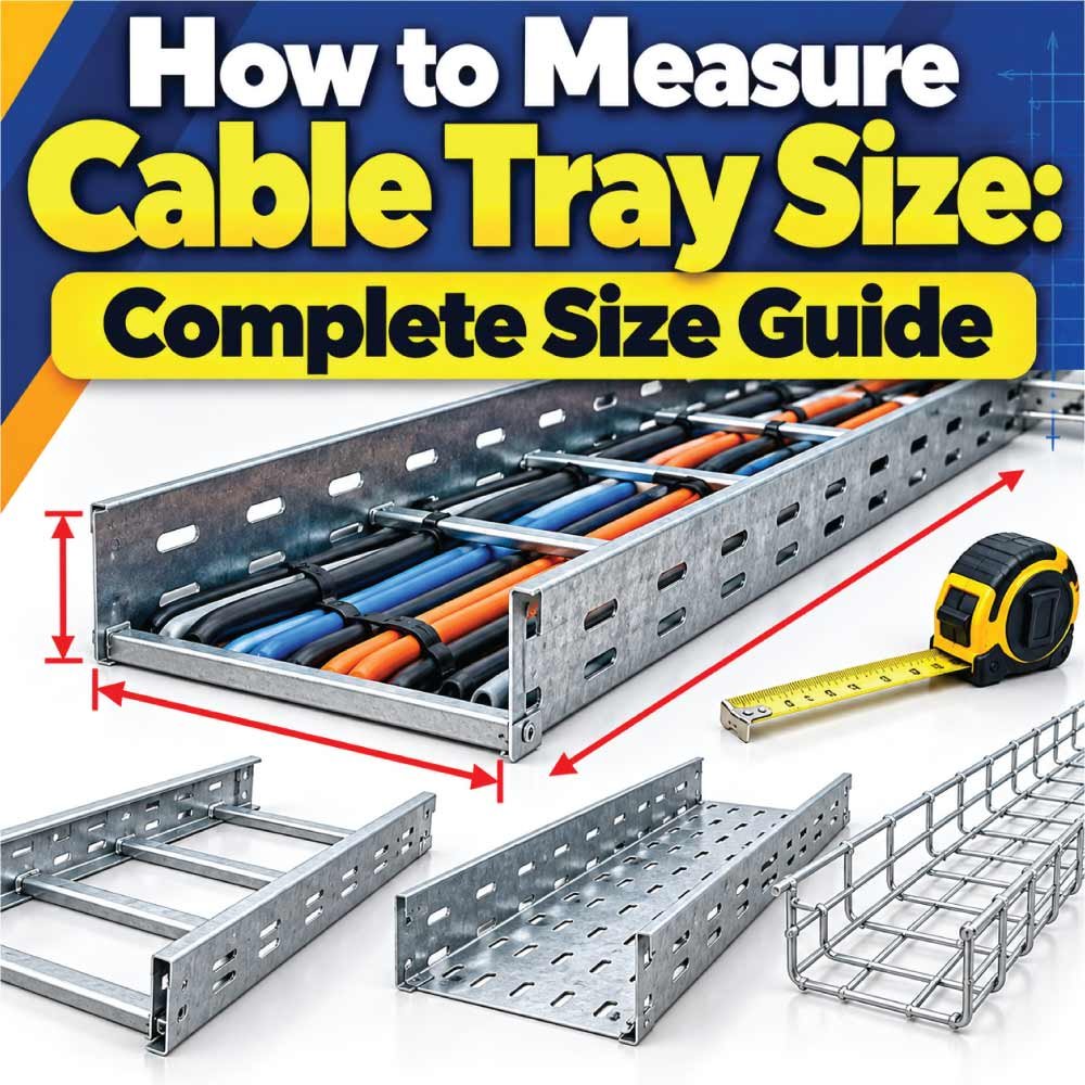
Choosing the correct cable tray size starts with more than measuring the available space. You need to account for the number and diameter of cables, required cable spacing, usable tray area, tray width and depth, future expansion, and installation conditions.
This guide explains how to measure cable tray size step by step, how to calculate cable fill, choose a suitable tray width and depth, and avoid common sizing mistakes. It also covers cable tray dimensions, fill calculations, cable arrangement, and practical selection considerations.
What Is Cable Tray Sizing?
Cable tray sizing is the process of determining the appropriate tray width, depth, length, and load capacity for the cables installed in an electrical system. The goal is to provide enough room for the cables without overcrowding the tray.
A cable tray may be made from ladder-type, perforated, solid-bottom, wire-mesh, or other construction styles. Regardless of the design, the basic sizing process begins with the cables that will occupy the tray.
The main factors include:
- Cable outside diameter
- Number of cables
- Cable arrangement
- Required spacing between cables
- Available tray width
- Usable tray depth
- Cable fill area
- Cable weight
- Support span
- Environmental conditions
- Future cable additions
- Applicable electrical codes and standards
A correctly sized tray should provide adequate physical space while also meeting the mechanical and electrical requirements of the installation.
Cable Tray Dimensions You Need to Measure
Before calculating tray size, understand the main dimensions used when selecting a tray.
Tray Width
Tray width is the horizontal distance available for cables. Common manufacturer offerings vary considerably, so the required width should be calculated rather than assumed.
Width depends primarily on:
- Number of cables
- Cable diameters
- Cable arrangement
- Required spacing
- Future capacity
For example, a tray carrying several large power cables may require substantially more width than a tray carrying small control cables.
Tray Depth
Tray depth is the vertical usable space inside the tray. It becomes particularly important when cables are arranged in layers or when the installation requires additional clearance.
The usable depth may be less than the overall manufactured depth because of the tray construction, fittings, covers, or installation arrangement.
Tray Length
Length does not normally determine the cross-sectional cable capacity. Instead, it is determined by the route from one point to another.
When measuring the required cable tray length, account for:
- Straight sections
- Horizontal bends
- Vertical bends
- Tees
- Crosses
- Risers
- Expansion requirements
- Termination points
How to Measure Cable Diameter
The cable’s outside diameter is one of the most important measurements for cable tray sizing.
For a single cable, use the actual outside diameter specified by the cable manufacturer whenever possible. Cable diameter can vary according to conductor size, insulation, shielding, armor, jacket construction, and cable type.
Do not assume that conductor size alone tells you the cable’s physical diameter.
Where to Find Cable Diameter
The outside diameter may be available in:
- Cable manufacturer datasheets
- Product catalogs
- Technical specifications
- Cable schedules
- Engineering drawings
If the actual cable is available, it can also be physically measured with a suitable measuring tool. Measure across the widest part of the cable without compressing its insulation or jacket.
For armored or multi-layer cables, measure the complete outside diameter rather than only the insulated conductor.
How to Calculate Cable Tray Size
The basic sizing process can be broken into several steps.
Step 1: Make a Cable List
Start by listing every cable that will occupy the tray.
Record:
| Cable Type | Quantity | Outside Diameter | Purpose |
|---|---|---|---|
| Power cable | 6 | Manufacturer data | Power |
| Control cable | 12 | Manufacturer data | Control |
| Instrument cable | 8 | Manufacturer data | Instrumentation |
The actual quantities and diameters should come from the project cable schedule or manufacturer documentation.
Step 2: Determine the Cable Arrangement
Next, decide how the cables will be positioned.
Cables may be:
- Arranged side by side
- Installed in multiple layers
- Grouped by circuit
- Separated according to project requirements
- Installed with physical separation between different cable types
The arrangement affects the required tray width and usable area.
For example, six cables installed in one horizontal row require a different tray configuration from six cables stacked vertically.
Step 3: Calculate the Required Cable Area
For a round cable, the approximate cross-sectional area can be calculated using:
Cable area = π × D² ÷ 4
Where:
- D = outside diameter of the cable
- π ≈ 3.1416
If multiple cables have the same diameter:
Total cable area = Cable area × Number of cables
For cables with different diameters, calculate each group separately and add the results.
For example, if a cable has an outside diameter of 20 mm:
Area = 3.1416 × 20² ÷ 4
This gives an approximate cross-sectional area of 314 mm².
The calculation is useful for understanding cable occupancy, but the final tray selection should also follow the applicable installation method and manufacturer’s recommendations.
Cable Tray Fill and Usable Area
Cable fill describes how much of the tray’s usable space is occupied by cables.
It is important to distinguish between the physical tray dimensions and the usable cable area. A tray that appears large enough from its outside dimensions may not provide sufficient usable space after accounting for its construction and installation requirements.
Why Cable Fill Matters
Excessive cable congestion can make installation and maintenance difficult. It may also interfere with cable routing, separation, heat dissipation, and future work.
When determining allowable fill, use the applicable electrical code, engineering specification, and cable tray manufacturer’s requirements. Different installations and cable arrangements can have different requirements.
A practical sizing calculation is therefore:
Required tray capacity ≥ calculated cable requirement + applicable clearance/fill allowance
Do not simply fill the entire internal volume of the tray.
How to Determine Cable Tray Width
Tray width is usually selected based on the horizontal arrangement of the cables.
For cables installed side by side, a basic conceptual calculation is:
Required width = Sum of cable diameters + required spacing
For example, if several cables have different diameters, add their outside diameters and then include any required separation or clearance.
| Cable | Quantity | Diameter | Width Contribution |
|---|---|---|---|
| Cable A | 4 | 20 mm | 80 mm |
| Cable B | 3 | 15 mm | 45 mm |
| Cable C | 5 | 10 mm | 50 mm |
| Total | 12 | — | 175 mm |
The 175 mm figure represents the sum of the cable diameters only. The final tray width must provide additional room where required by the cable arrangement, applicable rules, installation method, and future capacity.
After calculating the minimum requirement, select the next suitable standard tray width offered by the manufacturer rather than choosing a tray that exactly matches the calculated value.
How to Determine Cable Tray Depth
Tray depth becomes especially important when the installation requires multiple cable layers.
For a simple single-layer arrangement, the required depth may be relatively small compared with a multilayer installation. For multiple layers, consider the combined cable dimensions and the applicable fill requirements.
A simplified concept is:
Required tray depth ≥ cable layer height + required clearance
However, this should not be treated as a universal sizing rule. Cable type, tray configuration, loading method, and applicable standards can change the allowable arrangement.
Single-Layer Cable Installation
Single-layer installation places cables in one horizontal arrangement. This can simplify identification, maintenance, and heat management.
Multilayer Cable Installation
Multiple layers can increase tray utilization, but the design must account for cable size, weight, thermal considerations, and applicable installation requirements.
For large power cables, do not assume that stacking cables is acceptable simply because they physically fit.
Also Read:
Cable Tray Size Chart
The following table illustrates the types of dimensions that should be considered when comparing cable trays. It is a selection framework rather than a universal standard size chart, because manufacturers offer different dimensions and load ratings.
| Tray Width | Tray Depth | Typical Consideration |
|---|---|---|
| Narrow | Shallow | Small cable groups |
| Medium | Shallow | General cable routing |
| Medium | Deep | Larger cable volume |
| Wide | Medium | Multiple cable groups |
| Wide | Deep | High cable capacity and larger installations |
Always compare the manufacturer’s actual tray dimensions, usable area, loading data, and fittings before final selection.
How to Measure an Existing Cable Tray
If you already have a cable tray installed and want to determine its size, take several measurements.
Measure the Internal Width
Measure from the inside edge of one side rail to the inside edge of the opposite side rail.
This gives a more useful measurement than measuring the total outside width.
Measure the Internal Depth
Measure from the tray bottom to the lowest obstruction that limits usable cable space.
For trays with unusual profiles, covers, dividers, or fittings, identify the actual usable cable area.
Measure Cable Occupancy
Count the cables and measure or obtain their outside diameters.
Record the information in a table:
| Measurement | What to Record |
|---|---|
| Tray internal width | mm or inches |
| Tray internal depth | mm or inches |
| Cable quantity | Number |
| Cable diameter | mm or inches |
| Cable arrangement | Single or multiple layers |
| Tray length | Route measurement |
| Support spacing | Project/manufacturer requirement |
This information provides a starting point for evaluating whether the existing tray is suitable.
How to Choose the Correct Cable Tray Size
Cable tray selection should consider more than physical cable space.
Consider Cable Type
Power, control, instrumentation, communication, and other cable types can have different physical and installation requirements.
Identify the cable construction and application before selecting the tray.
Consider Cable Weight
A tray may have enough space for cables but still be unsuitable for their weight.
Check:
- Cable weight per unit length
- Tray load rating
- Support span
- Support configuration
- Fitting load considerations
The manufacturer’s loading information is important for the final design.
Consider Future Expansion
If the electrical system may expand, selecting a tray with no additional capacity can create problems later.
Future capacity should be based on the project requirements rather than an arbitrary percentage.
Consider the Installation Environment
Environmental conditions can affect tray material and construction.
Consider whether the installation is:
- Indoor
- Outdoor
- Wet
- Corrosive
- High temperature
- Exposed to sunlight
- Subject to mechanical impact
Material options can include steel, aluminum, stainless steel, and other finishes or constructions depending on the application.
Also Read:
Cable Tray Types and Their Sizing Considerations
Different tray designs can influence installation and selection.
Ladder Cable Tray
Ladder trays use longitudinal rails with transverse rungs. They are widely used for power and industrial cable routing.
Sizing considerations include cable diameter, width, weight, support spacing, and the way cables are secured to the rungs.
Perforated Cable Tray
Perforated or ventilated trays have a continuous base with openings.
They can provide cable support while allowing ventilation. The actual usable area depends on the tray design.
Solid Bottom Cable Tray
Solid-bottom trays provide a continuous base. They may be selected where additional cable support or protection is desired.
Wire Mesh Cable Tray
Wire-mesh trays use a grid-like structure and are commonly useful for smaller cables and flexible routing.
The cable quantity, diameter, weight, and tray construction still need to be considered during sizing.
Common Cable Tray Sizing Mistakes
Incorrect sizing often results from focusing only on tray width.
Common mistakes include:
- Measuring conductor size instead of cable outside diameter
- Ignoring cable quantity
- Assuming the entire tray depth is usable
- Forgetting cable separation requirements
- Ignoring cable weight
- Choosing a tray with no room for future additions
- Using nominal tray dimensions without checking internal dimensions
- Mixing measurement units
- Ignoring bends and fittings when planning the route
- Selecting tray material without considering the environment
- Treating a general sizing formula as a substitute for applicable standards
The most reliable approach is to combine the cable schedule, manufacturer data, tray specifications, and project requirements.
Also Read:
Cable Tray Sizing Example
Suppose an installation requires several cables with known outside diameters.
The process would be:
- List every cable.
- Record the quantity of each cable.
- Obtain the outside diameter of each cable.
- Calculate the cross-sectional area where relevant.
- Determine the intended cable arrangement.
- Calculate the required horizontal width.
- Determine the required tray depth.
- Check cable fill requirements.
- Check cable weight against tray capacity.
- Select a suitable standard tray size.
- Verify support spacing and installation requirements.
- Allow for project-approved future capacity where required.
This method is more reliable than selecting a tray based only on the number of cables.
How Much Extra Space Should a Cable Tray Have?
There is no single extra-space value that applies to every cable tray installation.
The required allowance depends on the applicable electrical code, cable type, installation arrangement, project specification, and manufacturer’s instructions.
Instead of assuming a fixed spare percentage, determine the project’s future requirements first.
Extra capacity can be valuable because it can make:
- Future cable installation easier
- Cable identification simpler
- Maintenance more convenient
- Routing changes easier
- Expansion less disruptive
However, adding unnecessary tray capacity can increase material and installation costs. The objective is to achieve an appropriate balance between present requirements and planned expansion.
Cable Tray Measurement Tips
For better sizing results, follow these practical tips:
- Use actual cable outside diameters whenever available.
- Keep all measurements in one unit system during calculations.
- Separate cable groups when the installation requires separation.
- Check both physical space and load capacity.
- Measure internal tray dimensions rather than relying only on external dimensions.
- Consider fittings and changes in direction.
- Review the manufacturer’s tray data.
- Check applicable electrical standards for the installation location.
- Plan future expansion according to the actual project needs.
- Recheck calculations before ordering materials.
For large commercial, industrial, or high-voltage installations, final cable tray sizing should be reviewed by a qualified electrical designer or engineer.
Frequently Asked Questions About Cable Tray Size
How do I calculate cable tray size?
Start by determining the number and outside diameter of all cables. Calculate the required cable area or horizontal arrangement, then select a tray width and depth that satisfy applicable fill, spacing, loading, and installation requirements.
What determines cable tray width?
Cable quantity, cable diameter, cable arrangement, required separation, and future capacity are major factors affecting tray width.
How do I measure an existing cable tray?
Measure the tray’s internal width and usable depth, then count the cables and determine their outside diameters. Also record tray length, support arrangement, and cable loading information where needed.
Does cable diameter matter for tray sizing?
Yes. Cable outside diameter directly affects how much physical space the cable occupies. Conductor size by itself is not enough to determine the required tray dimensions.
Can cables be stacked in a cable tray?
Cable stacking depends on the cable type, installation method, applicable requirements, tray design, loading, and thermal considerations. Do not assume that physically fitting multiple layers automatically makes the arrangement acceptable.
Should I allow space for future cables?
Where future expansion is expected, additional capacity can be incorporated into the design. The amount should be based on project requirements rather than an arbitrary allowance.
Is cable tray width the same as usable cable space?
Not necessarily. The nominal or overall tray width may differ from the usable internal width because of the tray construction, side rails, dividers, fittings, or other components.
Conclusion
Learning how to measure cable tray size requires more than measuring tray width. Start with the number, type, and outside diameter of the cables, determine their arrangement and required space, and then verify tray depth, fill, weight capacity, support conditions, and environmental requirements.
The best tray is not simply the smallest one that fits the cables. It should provide appropriate working space, meet applicable requirements, support the cable load, and accommodate planned installation needs. Always verify the final selection against the manufacturer’s specifications and applicable electrical standards before installation.