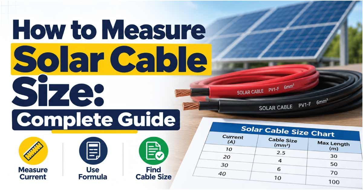
Choosing the right solar cable is essential for a safe and efficient photovoltaic (PV) system. A cable that is too small can create excessive voltage drop, generate heat, reduce system performance, and potentially become a safety hazard. A cable that is unnecessarily large, however, can increase installation costs without providing a meaningful benefit.
If you need to know how to measure solar cable size, the process involves more than simply measuring the outside diameter. Solar cable sizing depends on the conductor’s cross-sectional area, current capacity, cable length, voltage, allowable voltage drop, installation conditions, and the type of solar system.
This guide explains practical ways to identify and measure solar cable size, including how to measure cable diameter, calculate conductor area, read cable markings, understand mm² and AWG sizes, and select an appropriate cable for a PV installation.
What Does Solar Cable Size Mean?
Solar cable size normally refers to the cross-sectional area of the conductor, expressed in square millimeters (mm²). In some markets, wire sizes are also identified using American Wire Gauge (AWG).
For example, a solar cable may be marked:
- 2.5 mm²
- 4 mm²
- 6 mm²
- 10 mm²
- 16 mm²
- 25 mm²
The size describes the conductive metal inside the insulation, not the complete outside diameter of the finished cable.
This distinction is important because insulation thickness varies between cable types. Two cables can have similar outside diameters while having different conductor sizes.
For most metric solar installations, mm² is the more useful measurement for identifying conductor size.
Conductor Size vs. Cable Diameter
There are two measurements people commonly confuse:
Conductor diameter: The diameter of the bare metal conductor.
Overall cable diameter: The diameter from the outside of the insulation on one side to the outside on the other side.
The overall diameter includes insulation and, depending on cable construction, other layers. Therefore, measuring the outside of a solar cable does not directly tell you its electrical conductor size.
Why Correct Solar Cable Sizing Matters
Solar panels produce direct current (DC), and the cables connecting modules, combiner equipment, charge controllers, batteries, and inverters must safely carry the expected current.
Incorrect cable sizing can cause several problems:
- Excessive voltage drop
- Reduced electrical efficiency
- Cable heating
- Higher power losses
- Difficult connections
- Premature insulation damage
- Potential fire hazards in severe conditions
- Poor performance from the solar installation
The correct cable size also depends on the distance between components. A cable that works well over a short distance may not be suitable over a much longer run because voltage drop increases with cable length.
For this reason, measuring the existing cable is useful for identification, but it should not be the only method used to determine whether the cable is appropriate for a new installation.
How to Measure Solar Cable Size Step by Step
There are several ways to determine the size of a solar cable. The best method depends on whether the cable is labeled, installed, or available for direct measurement.
1. Check the Cable Markings
The easiest method is to inspect the printing along the cable jacket.
Solar cables commonly have markings that identify information such as:
- Conductor size
- Voltage rating
- Temperature rating
- Cable standard
- Manufacturer
- Cable type
- Certification markings
A cable may have a marking containing a value such as 4 mm² or 6 mm².
If the size is clearly printed on the cable, there is usually no need to calculate it from the diameter.
However, cable markings can become difficult to read after years of outdoor exposure. Dirt, UV exposure, abrasion, or installation conditions may make the printing unclear.
2. Disconnect and Isolate the Cable
If you need to physically measure a cable, electrical safety comes first.
A solar PV system can produce voltage whenever the panels are exposed to light. Do not cut, strip, or disconnect an energized solar cable simply to measure it.
Before working on installed wiring, follow the applicable isolation and electrical safety procedures. If you are unsure whether a circuit is de-energized, use a qualified electrician or solar installer.
3. Strip a Small Section if Appropriate
If the cable is disconnected and safe to work on, a small section of insulation can be removed to expose the conductor.
This method is more accurate than measuring the complete cable because the conductor itself is what determines the electrical cross-sectional area.
For stranded solar cable, avoid damaging or removing individual strands while exposing the conductor.
4. Measure the Conductor Diameter
Use a digital caliper or micrometer to measure the diameter of the conductor.
For a round solid conductor, the diameter can be used to calculate the cross-sectional area:
A = π × d² ÷ 4
Where:
- A = conductor cross-sectional area
- d = conductor diameter
- π ≈ 3.1416
For example, if a conductor were a solid round wire with a measured diameter of 2 mm:
A = 3.1416 × 2² ÷ 4
A ≈ 3.14 mm²
This calculation is straightforward for a solid conductor. Solar cables, however, are commonly stranded, so measuring diameter alone may not provide an exact nominal cable size.
5. Count the Strands
For a stranded conductor, you can improve identification by examining its construction.
If the strands are approximately the same diameter, measure the diameter of one strand and count the number of strands.
The approximate total metal cross-sectional area can then be calculated as:
A = n × π × d² ÷ 4
Where:
- n = number of strands
- d = diameter of one strand
The result should be treated as an identification aid rather than a replacement for the manufacturer’s specification. Strand dimensions, compaction, plating, manufacturing tolerances, and conductor construction can affect the result.
Solar Cable Size Measurement Table
The following table shows common metric cable sizes and approximate equivalent solid-conductor diameters calculated from cross-sectional area. These diameter values are mathematical equivalents and should not be treated as the actual diameter of a stranded solar cable.
| Nominal Size (mm²) | Approx. Solid Diameter (mm) | Typical Identification |
|---|---|---|
| 1.5 | 1.38 | Small conductor |
| 2.5 | 1.78 | Small PV wiring |
| 4 | 2.26 | Common PV size |
| 6 | 2.76 | Common PV size |
| 10 | 3.57 | Larger PV runs |
| 16 | 4.51 | Higher-current applications |
| 25 | 5.64 | Large conductors |
| 35 | 6.68 | High-current applications |
| 50 | 7.98 | Larger DC systems |
The actual outside diameter of a finished solar cable will be larger because it includes insulation and may have additional construction layers.
How to Measure Solar Cable Diameter
If your goal is specifically to determine solar cable diameter, use a caliper rather than a ruler.
Place the caliper across the outside of the cable jacket without squeezing the insulation excessively. Record the measurement in millimeters.
For example, you might measure:
Overall cable diameter = 6.5 mm
This tells you the physical diameter of the finished cable, but it does not necessarily mean the conductor is 6.5 mm or that the cable is a particular mm² size.
Why Outside Diameter Is Not Enough
Cable manufacturers can use different insulation thicknesses and constructions. Therefore:
Overall diameter ≠ conductor cross-sectional area
If the cable jacket is marked PV1-F, 4 mm², for example, the 4 mm² designation refers to the conductor’s nominal cross-sectional area, not the entire cable’s outside diameter.
Use the cable marking or manufacturer datasheet whenever possible.
How to Determine Solar Cable Size Without Stripping It
You may not always be able to remove the insulation. Fortunately, there are several non-destructive identification methods.
Read the Jacket Printing
Look carefully along the cable. Rotate it if necessary because markings may be printed on only one side.
Look for:
- mm² conductor size
- Cable designation
- Manufacturer name
- Voltage rating
- Temperature information
- Applicable standards or certifications
This is normally the preferred approach because it avoids damaging the cable.
Measure the Overall Diameter
If the cable marking is unreadable, measure the outside diameter with a caliper.
Then compare the measurement with the manufacturer’s cable datasheet. Do not rely solely on a generic diameter-to-size chart because insulation thickness and cable construction vary.
Inspect the Connector
Solar connectors can sometimes provide clues about the cable size they accommodate, but connector appearance alone should not be treated as definitive proof of conductor size.
For reliable identification, verify the cable marking or manufacturer’s documentation.
What Factors Determine Solar Cable Size?
Knowing the physical size of an existing cable is only one part of cable selection. To choose the correct size for a solar system, several electrical and installation factors need to be considered.
1. Current
The cable must be capable of carrying the expected current under the applicable installation conditions.
For PV circuits, use the electrical characteristics provided by the solar module, inverter, charge controller, battery system, or other equipment involved.
The cable’s allowable current depends not only on conductor size but also on installation conditions and the applicable electrical requirements.
2. Cable Length
Longer cables have greater electrical resistance and therefore produce more voltage drop.
This is particularly important on low-voltage DC systems. A relatively small voltage drop can represent a significant percentage of the system voltage.
For example, voltage drop that is modest in a higher-voltage circuit may be much more significant in a 12 V battery-based solar system.
3. System Voltage
Solar systems may operate at different DC voltages, including low-voltage battery systems and higher-voltage PV strings.
For the same power requirement:
Higher voltage generally means lower current.
Because cable heating and voltage drop are strongly related to current, system voltage is an important part of cable sizing.
4. Installation Conditions
Cable capacity can be affected by conditions such as:
- Ambient temperature
- Bundling
- Conduit installation
- Direct exposure
- Number of loaded conductors
- Installation method
- Surrounding materials
The applicable electrical code and cable manufacturer’s specifications should be used when determining allowable ampacity.
How to Calculate Solar Cable Voltage Drop
Voltage drop is one of the most important considerations when selecting a solar cable.
For a simple two-conductor DC circuit, voltage drop can be estimated using:
Vd = I × R
Where:
- Vd = voltage drop
- I = current
- R = total circuit resistance
Resistance depends on conductor material, cross-sectional area, temperature, and total conductor length.
For a basic copper-conductor calculation:
R = ρ × L ÷ A
Where:
- ρ = resistivity of the conductor material
- L = total conductor length
- A = conductor cross-sectional area
For a DC circuit, remember that current travels out through one conductor and returns through another. Therefore, the relevant electrical path can be approximately twice the one-way distance when calculating a two-wire circuit.
Actual system design should account for the applicable temperature, conductor construction, connection resistance, installation method, and manufacturer’s data.
Solar Cable Size Selection Example
Suppose you have a small DC solar installation where the cable run between equipment is relatively long.
You know:
- The system voltage
- The expected operating current
- The one-way cable distance
- The acceptable voltage drop
- The cable material
- The installation method
You can then compare different conductor sizes.
A simplified selection process looks like this:
- Determine the expected operating and maximum relevant current.
- Determine the one-way cable length.
- Establish the acceptable voltage-drop limit based on the system design.
- Calculate or verify voltage drop.
- Check the cable’s allowable current under the actual installation conditions.
- Check the cable manufacturer’s specifications.
- Verify connector compatibility.
- Select the cable size that satisfies all applicable requirements.
The largest cable is not automatically the correct cable, and the smallest cable that carries the current is not necessarily appropriate either. Voltage drop, temperature, installation conditions, and applicable requirements all matter.
Common Solar Cable Sizes and Applications
There is no single cable size that is correct for every solar installation. Common sizes are used for different applications depending on current, distance, and system design.
| Cable Size | Possible Application | Important Consideration |
|---|---|---|
| 2.5 mm² | Smaller PV or control-related wiring | Verify current and installation conditions |
| 4 mm² | Many residential PV connections | Check current and cable length |
| 6 mm² | Higher-current PV connections | Useful where additional capacity or reduced voltage drop is required |
| 10 mm² | Longer or higher-current DC runs | Verify termination and connector compatibility |
| 16 mm²+ | Larger DC systems | Requires careful sizing and installation design |
These are general examples, not universal sizing recommendations. Actual cable selection must be based on the system’s electrical requirements and applicable standards.
Solar Cable mm² vs AWG
Solar cables may be specified in either metric sizes or AWG, depending on the market and equipment.
Metric sizing identifies the conductor using its cross-sectional area in square millimeters. AWG uses a different numbering system.
Because the systems are based on different sizing conventions, an AWG number should not simply be treated as an exact metric equivalent without checking a reliable conversion table or manufacturer specification.
| Metric Size | General AWG Range |
|---|---|
| 2.5 mm² | Approximately 13–14 AWG |
| 4 mm² | Approximately 11–12 AWG |
| 6 mm² | Approximately 9–10 AWG |
| 10 mm² | Approximately 7–8 AWG |
| 16 mm² | Approximately 5–6 AWG |
These are approximate comparison ranges rather than exact substitutions. When buying or replacing cable, use the exact conductor specification required by the equipment and applicable installation requirements.
Tools for Measuring Solar Cable Size
You do not need a large collection of equipment to identify a cable, but certain tools can make the process more accurate.
Useful Tools
- Digital caliper: Measures conductor or cable diameter accurately.
- Micrometer: Useful for precise conductor measurements.
- Wire stripper: Used to expose the conductor when the cable is safely disconnected.
- Ruler: Suitable for measuring cable length but less precise for diameter.
- Magnifying glass: Helpful when cable markings are difficult to read.
- Multimeter: Useful for electrical testing, but it does not directly measure conductor size.
- Manufacturer datasheet: Often the best reference for confirming actual cable construction.
A multimeter is especially important to distinguish from a cable-sizing tool. It can measure electrical properties such as voltage and resistance, but it does not directly tell you whether a conductor is 4 mm², 6 mm², or 10 mm².
Common Mistakes When Measuring Solar Cable
Measuring Only the Outside Diameter
This is probably the most common mistake. The jacket increases the cable’s overall diameter, so outside diameter does not directly identify conductor area.
Assuming Connector Size Equals Cable Size
A connector may be compatible with a range of cable sizes. Always verify the cable and connector specifications independently.
Ignoring Cable Length
A cable may carry the required current but still produce excessive voltage drop over a long distance.
Using a Generic Ampacity Chart Without Checking Conditions
Ampacity depends on installation conditions and applicable requirements. A chart from one application should not automatically be applied to another.
Confusing Wire Gauge With Diameter
AWG is a standardized gauge system, not simply a measurement of outside diameter.
Selecting Cable Based Only on Current
Current capacity is important, but so are voltage drop, temperature, installation method, connector compatibility, mechanical requirements, and applicable standards.
How to Choose the Right Solar Cable
After measuring an existing cable or planning a new installation, use a systematic approach.
Solar Cable Selection Checklist
Before purchasing or installing cable, verify:
- Conductor material
- Nominal cross-sectional area
- Cable voltage rating
- Temperature rating
- PV suitability
- Outdoor and UV suitability where required
- Expected current
- Cable length
- Voltage-drop requirements
- Installation method
- Connector compatibility
- Manufacturer documentation
- Applicable electrical standards
A cable intended specifically for PV applications is generally preferable to simply choosing an ordinary wire with a similar conductor size. Solar installations can expose cables to sunlight, temperature changes, moisture, and outdoor mechanical stresses, so the complete cable construction matters.
Frequently Asked Questions About Measuring Solar Cable Size
How do I know what size my solar cable is?
Start by reading the markings printed on the cable jacket. If the marking is unavailable, measure the conductor diameter after safely disconnecting and exposing it, then calculate or estimate its cross-sectional area. For stranded cable, manufacturer specifications provide a more reliable identification than diameter alone.
Can I measure solar cable size with a caliper?
Yes, a caliper can measure the conductor diameter or overall cable diameter. However, measuring the outside diameter alone does not establish the conductor’s mm² size. For stranded solar cable, use the manufacturer’s markings or datasheet whenever possible.
Is 4 mm² solar cable better than 6 mm²?
Neither is automatically better. The appropriate size depends on current, cable length, voltage, allowable voltage drop, installation conditions, and equipment requirements. A 6 mm² conductor has a larger cross-sectional area, but that does not mean it is necessary for every solar circuit.
Does longer solar cable need a larger size?
A longer cable run generally has greater resistance and can produce more voltage drop. Increasing conductor cross-sectional area reduces resistance. Therefore, a longer run may require a larger cable to keep voltage drop within the design limit, depending on the current and system voltage.
Can I use regular electrical wire for solar panels?
Not necessarily. PV wiring is exposed to environmental and electrical conditions that require suitable cable construction and ratings. Use cable specifically appropriate for the intended PV application and verify its voltage, temperature, environmental, and installation requirements before installation.
Final Thoughts on Measuring Solar Cable Size
Learning how to measure solar cable size starts with understanding the difference between conductor size and overall cable diameter. The most reliable identification method is usually the cable’s printed marking or manufacturer documentation. If those are unavailable, carefully measuring the conductor and calculating its approximate cross-sectional area can help identify the cable.
For a new solar installation, however, identification is only the beginning. Correct cable selection also requires checking current, system voltage, cable length, voltage drop, installation conditions, connector compatibility, and applicable electrical requirements.
When safety and performance matter, do not choose cable based solely on appearance or outside diameter. Verify the conductor specification and use the manufacturer’s data and applicable installation requirements to select the appropriate solar cable.