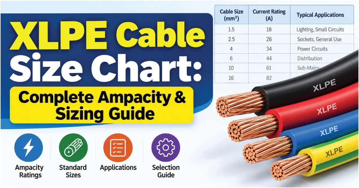
Choosing the correct XLPE cable size is essential for safe, efficient, and reliable power transmission. XLPE cables are widely used in residential, commercial, industrial, utility, and distribution systems because their insulation provides good thermal performance, electrical strength, and resistance to environmental conditions.
However, selecting an XLPE cable is not as simple as matching the cable size to the load current. The correct choice can depend on conductor material, voltage, number of cores, installation method, ambient temperature, permissible current, voltage drop, short-circuit conditions, and cable construction.
This XLPE cable size chart provides commonly used cable sizes and practical guidance for understanding conductor selection, current-carrying capacity, applications, and important sizing factors.
What Is an XLPE Cable?
XLPE stands for Cross-Linked Polyethylene. It is an insulation material used around electrical conductors in power cables.
Unlike conventional thermoplastic polyethylene, XLPE has a cross-linked molecular structure that gives it improved thermal and mechanical characteristics.
XLPE cables are commonly manufactured with:
- Copper or aluminum conductors
- XLPE insulation
- Inner sheath or bedding where applicable
- Armoring where required
- Outer protective sheath
- One or more cores
Depending on the cable design, XLPE cables can be used in low-voltage, medium-voltage, and higher-voltage power systems.
Their ability to operate at relatively high conductor temperatures makes XLPE insulation particularly useful for power-distribution applications.
XLPE Cable Size Chart
Cable sizes are commonly expressed in mm² for low- and medium-voltage power cables. The following chart shows common conductor sizes and typical applications.
| Cable Size (mm²) | Typical Conductor | Common Application |
|---|---|---|
| 1.5 mm² | Copper | Lighting and small circuits |
| 2.5 mm² | Copper | General branch circuits |
| 4 mm² | Copper | Small power loads |
| 6 mm² | Copper | Medium power circuits |
| 10 mm² | Copper/Aluminum | Feeders and equipment |
| 16 mm² | Copper/Aluminum | Distribution feeders |
| 25 mm² | Copper/Aluminum | Larger feeders |
| 35 mm² | Copper/Aluminum | Power distribution |
| 50 mm² | Copper/Aluminum | Higher-current feeders |
| 70 mm² | Copper/Aluminum | Industrial distribution |
| 95 mm² | Copper/Aluminum | Large feeders |
| 120 mm² | Copper/Aluminum | High-current distribution |
| 150 mm² | Copper/Aluminum | Large power systems |
| 185 mm² | Copper/Aluminum | Heavy-duty feeders |
| 240 mm² | Copper/Aluminum | High-capacity distribution |
| 300 mm² | Copper/Aluminum | Large industrial systems |
| 400 mm² | Copper/Aluminum | High-current power systems |
| 500 mm² | Copper/Aluminum | Major distribution systems |
| 630 mm² | Copper/Aluminum | Very high-current systems |
This is a size reference rather than a universal ampacity table. The allowable current for a particular XLPE cable depends on its construction and installation conditions.
XLPE Cable Current Carrying Capacity
The current carrying capacity, or ampacity, is one of the most important factors when selecting a cable.
It describes how much current a cable can continuously carry under specified conditions without exceeding its permitted conductor temperature.
A cable’s ampacity can change significantly depending on:
- Conductor material
- Number of cores
- Conductor size
- Installation method
- Ambient temperature
- Soil thermal resistivity for buried cables
- Number of loaded cables
- Cable spacing
- Enclosure or tray arrangement
- Insulation temperature rating
For this reason, a single ampacity number should not be applied to every XLPE cable installation.
Why XLPE Allows Higher Operating Temperatures
XLPE insulation is commonly designed for a 90°C maximum continuous conductor operating temperature under appropriate cable standards and conditions.
That thermal capability is one reason XLPE is widely used in power cables.
However, the 90°C insulation rating does not mean every installation automatically receives the 90°C ampacity. Cable standards, accessories, equipment terminals, installation conditions, and applicable regulations must still be considered.
XLPE Cable Size and Conductor Material
XLPE cables are commonly manufactured using either copper or aluminum conductors.
Copper XLPE Cable
Copper offers high electrical conductivity and is widely used where smaller conductor sizes, good termination characteristics, or higher conductivity are desirable.
Common copper XLPE sizes include:
- 1.5 mm²
- 2.5 mm²
- 4 mm²
- 6 mm²
- 10 mm²
- 16 mm²
- 25 mm²
- 35 mm²
- 50 mm²
- 70 mm²
- 95 mm²
- 120 mm²
- 150 mm²
- 185 mm²
- 240 mm²
- 300 mm² and larger
Aluminum XLPE Cable
Aluminum is frequently used for larger power-distribution cables because it is lighter and generally less expensive by conductor mass than copper.
Common aluminum XLPE sizes include:
- 16 mm²
- 25 mm²
- 35 mm²
- 50 mm²
- 70 mm²
- 95 mm²
- 120 mm²
- 150 mm²
- 185 mm²
- 240 mm²
- 300 mm²
- 400 mm²
- 500 mm²
- 630 mm²
For aluminum conductors, correct lugs, terminals, jointing methods, and installation practices are particularly important.
Discover More:
XLPE Cable Size by Number of Cores
XLPE cables are available in different core configurations.
| Cable Type | Number of Cores | Typical Use |
|---|---|---|
| 1-Core XLPE | 1 | High-current and specialized power systems |
| 2-Core XLPE | 2 | Single-phase power applications |
| 3-Core XLPE | 3 | Three-phase systems |
| 3.5-Core XLPE | 3 + reduced neutral | Three-phase distribution |
| 4-Core XLPE | 4 | Three-phase plus neutral |
| 5-Core XLPE | 5 | Three-phase, neutral, and protective conductor arrangements |
The correct number of cores depends on the electrical system and circuit design.
For example, a three-phase system may use a 3-core cable when a neutral is not required, while a four-core configuration can provide three phases plus neutral.
How to Choose the Correct XLPE Cable Size
Choosing the right cable size requires several calculations and checks.
1. Determine the Load Current
First determine the current required by the equipment or electrical system.
For three-phase systems, load current can be calculated using the appropriate relationship between power, voltage, efficiency, and power factor.
For a simplified three-phase load:
I = P / (√3 × V × PF × η)
Where:
- I = current
- P = power
- V = line voltage
- PF = power factor
- η = efficiency when applicable
The actual calculation depends on whether the specified load is electrical input power, mechanical output power, apparent power, or another quantity.
2. Select Copper or Aluminum
Determine whether copper or aluminum is appropriate for the project.
Copper may allow a smaller conductor for a given electrical requirement, while aluminum can offer weight and cost advantages for larger installations.
3. Determine the Number of Cores
Select the cable construction based on the circuit.
For example:
- Single-phase circuits may require two or more conductors.
- Three-phase circuits may use three, four, or five conductors depending on the system.
- Specialized installations may use single-core cables.
4. Check Installation Method
The same cable size can have different current-carrying capacity depending on whether it is:
- Installed in free air
- Installed on a cable tray
- Installed in conduit
- Buried directly
- Installed in ducts
- Grouped with other cables
Installation conditions must therefore be included in cable selection.
Discover More:
XLPE Cable Size and Voltage Drop
Voltage drop is another important consideration when selecting cable size.
As cable length increases, resistance causes voltage to decrease between the supply point and the load.
A cable can therefore have sufficient current-carrying capacity but still require a larger conductor to keep voltage drop within the desired or required limit.
Voltage drop depends on:
- Cable length
- Load current
- Conductor resistance
- Conductor material
- Cable size
- Power factor
- System voltage
- Circuit configuration
For long-distance feeders, increasing the conductor size can reduce resistance and improve voltage regulation.
Example
Suppose two cables carry the same load current, but one cable run is significantly longer.
The longer cable will generally experience greater voltage drop. Instead of selecting the conductor solely from an ampacity chart, the designer should calculate voltage drop and determine whether a larger cable is necessary.
XLPE Cable Size for Different Voltage Systems
XLPE insulation is used across different voltage classes, but cable construction changes according to the system voltage.
Low-Voltage XLPE Cable
Low-voltage XLPE cables are commonly used for:
- Building power distribution
- Industrial feeders
- Control and equipment power
- Distribution boards
- Motors
- Generators
Typical sizes can range from relatively small conductors to several hundred square millimeters.
Medium-Voltage XLPE Cable
Medium-voltage cables have additional construction requirements compared with ordinary low-voltage cables.
They may include:
- XLPE insulation
- Conductor screen
- Insulation screen
- Metallic screen
- Protective sheath
- Armor where required
Medium-voltage cable selection must consider the voltage class, insulation thickness, fault current, screen requirements, installation method, and accessories.
High-Voltage Applications
Higher-voltage XLPE cable systems require specialized engineering.
Cable design can involve:
- Electrical stress control
- Metallic shielding
- Sheath bonding
- Short-circuit withstand
- Installation configuration
- Thermal characteristics
- Jointing and termination systems
For these installations, manufacturer data and the applicable cable standard should be used rather than a general size chart.
XLPE Cable Applications
XLPE cables are widely used because of their electrical and thermal characteristics.
Typical applications include:
- Residential power distribution
- Commercial buildings
- Industrial plants
- Power stations
- Utility distribution networks
- Transformers
- Motors
- Generators
- Switchgear connections
- Underground power systems
- Cable trays
- Distribution feeders
- Renewable-energy installations
The specific cable construction should always match the environment and electrical system.
XLPE vs PVC Cable
One common comparison is XLPE vs PVC insulation.
| Feature | XLPE | PVC |
|---|---|---|
| Insulation Type | Cross-linked polyethylene | Polyvinyl chloride |
| Typical Conductor Temperature Rating | 90°C | Often lower, depending on cable type |
| Thermal Performance | High | Moderate |
| Power Distribution | Widely used | Widely used |
| Current Capacity | Often favorable | Depends on design |
| Typical Applications | Power and distribution | General wiring and power |
| Environmental Performance | Depends on sheath and formulation | Depends on formulation |
Neither insulation type is automatically better for every application. The appropriate choice depends on cable requirements, environmental conditions, voltage, installation method, cost, and applicable standards.
Discover More:
XLPE Cable Size and Short-Circuit Rating
Normal operating current is not the only electrical condition that matters.
During a short circuit, a cable can experience extremely high current for a short period. The conductor and insulation system must be capable of withstanding the associated thermal and mechanical stresses for the specified fault-clearing time.
Short-circuit withstand depends on:
- Conductor material
- Conductor cross-sectional area
- Initial conductor temperature
- Final permitted temperature
- Fault duration
- Cable construction
For large power cables, short-circuit calculations can be an important part of cable selection.
Armored vs Unarmored XLPE Cable
XLPE cables can be manufactured with or without armor depending on the installation.
Armored XLPE Cable
Armored cables can provide additional mechanical protection and may be used for:
- Underground installations
- Industrial environments
- Direct-burial systems where permitted
- Areas with increased mechanical risk
Unarmored XLPE Cable
Unarmored cables may be suitable where the installation method already provides adequate mechanical protection.
For example, cables installed in appropriate protected cable systems may not require armor.
The choice should be based on the installation environment and applicable requirements rather than cable size alone.
Common XLPE Cable Sizing Mistakes
Several mistakes can result in an incorrectly selected cable.
Ignoring Installation Conditions
A cable’s ampacity depends heavily on how and where it is installed.
Using Only the Conductor Size
Two cables with the same conductor cross-sectional area can have different ratings because of their construction, insulation, number of cores, and installation conditions.
Ignoring Voltage Drop
Long cable runs may require a larger conductor even when ampacity is adequate.
Ignoring Grouping
Multiple cables installed close together can increase heat accumulation and reduce allowable current.
Confusing Cable Size With Outer Diameter
A cable marked 95 mm² refers to the conductor cross-sectional area, not the overall outside diameter of the finished cable.
Using a Low-Voltage Chart for Medium Voltage
Medium-voltage and higher-voltage cables have different construction and engineering requirements. A general low-voltage cable chart should not be used to select them.
XLPE Cable Size FAQs
What is XLPE cable used for?
XLPE cable is widely used for electrical power transmission and distribution in residential, commercial, industrial, and utility applications. It can be manufactured for low-, medium-, and higher-voltage systems, with construction varying according to voltage, installation environment, conductor material, and applicable cable standards.
What does XLPE mean in cable?
XLPE means Cross-Linked Polyethylene, which is the insulation material surrounding the electrical conductor. Cross-linking changes the material’s structure and provides useful thermal, electrical, and mechanical characteristics for power-cable applications.
Is XLPE cable better than PVC cable?
XLPE can provide higher thermal performance than many PVC-insulated cable designs and is widely used for power distribution. However, the better choice depends on the application, temperature requirements, environmental conditions, cost, cable construction, and applicable standards.
What is the difference between XLPE and XLPE armored cable?
An XLPE cable describes the insulation system, while an armored XLPE cable additionally includes a protective metallic armor layer. Armor can provide mechanical protection for installations where the cable may be exposed to physical stress or damage.
How is XLPE cable size selected?
XLPE cable size is selected by considering load current, conductor material, voltage, number of cores, installation method, ambient conditions, grouping, voltage drop, short-circuit withstand, and applicable standards. The manufacturer’s technical data should then be used to verify the selected cable.
Final Thoughts on XLPE Cable Size
The correct XLPE cable size depends on the complete electrical and installation design rather than conductor area alone. Common sizes range from small 1.5 mm² and 2.5 mm² conductors to very large 500 mm² and 630 mm² cables, but the appropriate size depends on the load and installation conditions.
When selecting an XLPE cable, evaluate ampacity, voltage drop, conductor material, number of cores, installation method, ambient temperature, grouping, short-circuit withstand, voltage class, and cable construction.
Use a manufacturer’s cable datasheet and the applicable electrical standard for the final selection. For medium-voltage, high-voltage, or high-current systems, professional electrical design and verification are especially important.