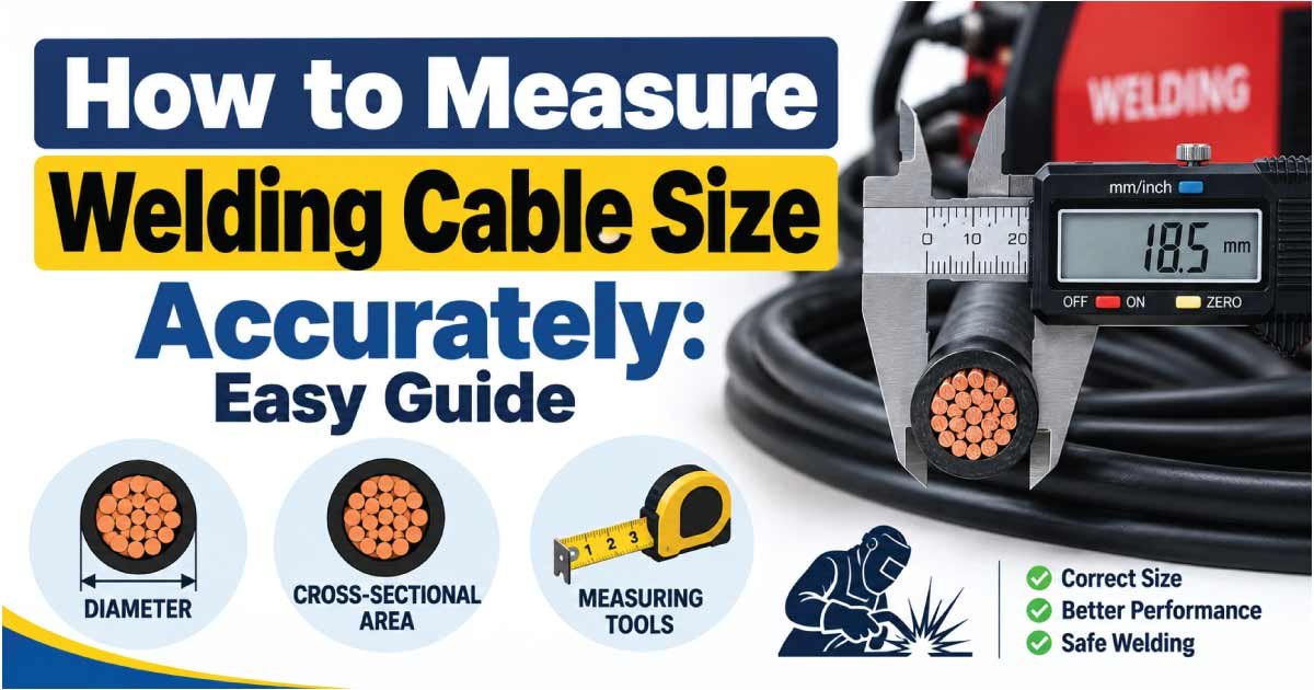
Choosing the correct welding cable size is important for safe, reliable welding performance. A cable that is too small can create excessive voltage drop, overheating, and unnecessary power loss, while an unnecessarily large cable can add cost, weight, and installation difficulty.
The good news is that measuring welding cable size does not have to be complicated. You can identify the cable by its diameter, determine its conductor cross-sectional area, or use the cable’s marked gauge or size designation. However, physical measurement alone is not enough when selecting a replacement cable. Welding current, cable length, duty cycle, insulation type, and the welding machine’s requirements also matter.
This guide explains how to measure welding cable size accurately, how cable diameter relates to conductor size, how to convert measurements, and how to select a suitable cable for different welding applications.
What Is Welding Cable Size?
Welding cable size describes the electrical conductor’s capacity and physical dimensions. Unlike ordinary building wire, welding cable is designed to remain flexible while carrying substantial welding current in demanding environments.
Welding cables are commonly identified using:
- AWG (American Wire Gauge) sizes
- Cross-sectional area in mm²
- Manufacturer-specific size designations
- Printed markings on the cable jacket
The size refers primarily to the conductive copper area, not simply the outside diameter of the complete cable.
For example, two cables can have similar outside diameters but different conductor areas because their insulation thicknesses differ. This is why measuring only the outside of an insulated welding cable does not provide an exact conductor size.
Why Welding Cable Size Matters
The cable must be capable of carrying the required welding current without excessive heating or voltage loss.
An appropriately sized cable helps provide:
- Reliable current delivery
- Lower voltage drop
- Reduced heat generation
- Better welding performance
- Longer cable service life
- Safer operation
The correct size depends on the complete welding circuit rather than amperage alone.
Tools Needed to Measure Welding Cable Size
You can measure welding cable with a few simple tools. The method you choose depends on whether the cable is insulated or already stripped.
Useful tools include:
- Digital caliper for measuring conductor or cable diameter
- Ruler or tape measure for approximate outside diameter
- Wire gauge tool for identifying AWG
- Micrometer when greater measurement precision is needed
- Calculator for cross-sectional-area calculations
- Cable manufacturer’s markings or datasheet for verification
If the cable has printed markings, check those first. The manufacturer’s identification is usually more reliable than estimating the conductor size from outside diameter.
How to Measure Welding Cable Size Step by Step
The most reliable approach is to identify the conductor size rather than relying solely on the jacket diameter.
1. Disconnect and Isolate the Cable
Before measuring, make sure the welding machine is switched off and the cable is disconnected from the power source.
Never measure or handle exposed conductors while the welding circuit is energized.
If the cable is part of an installed welding system, follow the equipment manufacturer’s isolation procedures before inspecting it.
2. Check the Cable Markings
Look along the cable jacket for printed information. Depending on the manufacturer, markings may identify:
- Cable size
- AWG designation
- Conductor area
- Voltage rating
- Temperature rating
- Manufacturer
- Welding cable type
- Applicable standards
A marking such as 2 AWG, for example, identifies the conductor according to the American Wire Gauge system.
A marking such as 50 mm² indicates the approximate conductor cross-sectional area.
When readable markings are available, use them as the starting point and verify the information against the manufacturer’s documentation.
3. Measure the Outside Diameter
If the cable markings are missing or unreadable, measure the outside diameter with a caliper.
Place the caliper around the complete insulated cable without squeezing the insulation excessively.
Record the measurement in millimeters or inches.
However, remember that outside diameter is not the same as conductor diameter. The result includes the insulation and any other outer layers.
Therefore, outside diameter is useful for identification and comparison, but it should not normally be used by itself to determine the electrical conductor size.
4. Measure the Conductor Diameter if Accessible
If the cable end is already stripped and the conductor is accessible, you can obtain a more useful measurement.
For a round conductor, measure the conductor’s diameter across the copper strands or equivalent conductor area.
Because welding cable is normally made from many fine strands, measuring individual strands is not the same as measuring the entire conductor. Avoid compressing the strands during measurement.
If the conductor is highly flexible and consists of numerous fine wires, the most accurate method is often to determine the total cross-sectional area from the cable marking or manufacturer specification.
5. Calculate Cross-Sectional Area for a Solid Round Conductor
For a solid round conductor, cross-sectional area can be calculated using:
A = π × d² ÷ 4
Where:
- A = cross-sectional area
- d = conductor diameter
- π ≈ 3.1416
For example, if a solid conductor has a diameter of 6 mm:
A = 3.1416 × 6² ÷ 4
A ≈ 28.3 mm²
This calculation works well for a solid round conductor. However, welding cable is normally stranded, so a direct diameter measurement across the complete bundle may not provide an exact area.
6. Compare the Result With a Standard Size
Once you have the conductor area, compare it with a recognized cable size or the manufacturer’s published specifications.
Do not automatically round to the nearest size if the cable will carry a high welding current. For an actual installation, the cable should be selected according to the applicable electrical requirements and equipment documentation.
Welding Cable Size Chart: AWG and Metric Area
The following table provides commonly encountered nominal conductor areas for reference. AWG and metric sizes are not exact one-to-one equivalents, so treat the metric values as nominal comparisons rather than interchangeable specifications.
| AWG Size | Nominal Area (mm²) | Typical Use Consideration |
|---|---|---|
| 6 AWG | 13.3 mm² | Smaller welding circuits |
| 4 AWG | 21.2 mm² | Light to moderate current applications |
| 2 AWG | 33.6 mm² | Medium to higher current applications |
| 1 AWG | 42.4 mm² | Higher current circuits |
| 1/0 AWG | 53.5 mm² | Heavy-duty welding applications |
| 2/0 AWG | 67.4 mm² | High-current applications |
| 3/0 AWG | 85.0 mm² | Very high-current applications |
| 4/0 AWG | 107.2 mm² | Heavy-duty, high-current circuits |
These figures describe conductor cross-sectional area, not the complete outside diameter of the finished welding cable. Actual outside dimensions vary by manufacturer, insulation construction, strand configuration, and cable design.
How to Measure Welding Cable Diameter
Cable diameter is one of the easiest physical measurements to obtain, but it must be interpreted correctly.
Measuring Insulated Cable Diameter
Use a digital caliper and measure across the outside of the cable.
For a flexible cable:
- Disconnect the cable.
- Clean dirt or debris from the jacket.
- Place the caliper around the cable.
- Apply light, consistent pressure.
- Record the measurement.
- Take measurements at several points if the cable appears irregular.
Avoid crushing the insulation because excessive pressure can produce a smaller measurement.
Measuring Stranded Conductor Diameter
A stranded welding cable does not behave like a solid wire. The spaces between individual strands mean that the outside diameter of the strand bundle does not directly equal its total copper area.
For this reason, conductor cross-sectional area or manufacturer specifications are preferable to diameter alone when determining electrical capacity.
How Welding Cable Size Relates to Amperage
One of the most common mistakes is assuming that a specific amperage always requires one specific cable size.
In reality, welding cable selection depends on several variables.
Current
Higher welding current generally requires a larger conductor to limit heating and voltage drop.
A cable used for a lower-current application may not be suitable for a higher-current welding machine, even if the cable physically fits the terminals.
Cable Length
Longer cables create greater resistance and therefore greater voltage drop.
For example, a welding circuit using a relatively short electrode and work lead may have different requirements from a system using very long cables.
When determining total circuit length, consider both sides of the welding circuit. The electrode cable and work-return cable together form the current path.
Duty Cycle
Welding machines do not necessarily operate at their maximum rated current continuously.
Duty cycle describes how long equipment can operate at a specified output during a defined period. Cable selection must account for the actual operating conditions rather than simply looking at the machine’s maximum possible output.
Ambient Temperature and Installation Conditions
Heat surrounding the cable can affect its operating conditions. Cables bundled together, exposed to high temperatures, or installed in restricted areas may have different allowable operating conditions from a freely exposed cable.
Always follow the cable manufacturer’s rating and applicable requirements.
What Size Welding Cable Do You Need?
There is no universal cable size that is correct for every welding machine.
Instead, determine the requirements of the specific welding circuit.
Consider:
- Welding current
- Cable length
- Electrode lead length
- Work lead length
- Duty cycle
- Cable construction
- Insulation rating
- Ambient temperature
- Installation conditions
- Welding equipment specifications
- Applicable electrical standards
A manufacturer’s welding cable chart can be particularly useful because it can relate cable size to current, length, and duty cycle for the intended cable construction.
Why Larger Is Not Always Better
Using a larger cable can reduce electrical resistance, but it also increases:
- Weight
- Cost
- Handling difficulty
- Connector size requirements
- Storage requirements
The objective is not simply to install the largest cable possible. The objective is to use a cable that is appropriately rated for the actual application.
Welding Cable vs Battery Cable
Welding cable and battery cable can appear similar because both are commonly flexible, stranded conductors.
However, they are not automatically interchangeable.
Welding Cable
Welding cable is specifically designed for welding applications and typically emphasizes:
- Flexibility
- Fine stranding
- Resistance to mechanical handling
- Suitability for welding circuits
- Appropriate insulation for the intended environment
Battery Cable
Battery cables are designed primarily for battery and vehicle electrical systems. Their construction, insulation, temperature rating, flexibility, and intended application can differ from welding cable.
When replacing a welding cable, use a cable specifically suitable for the welding application rather than selecting a cable based only on its diameter or copper content.
Common Mistakes When Measuring Welding Cable
Incorrect measurement can result in selecting a cable that is unsuitable for the application.
Mistake 1: Measuring Only the Insulation
The outside diameter includes insulation, so it does not directly tell you the copper cross-sectional area.
Mistake 2: Confusing Diameter With Area
A small increase in conductor diameter can produce a significantly larger change in cross-sectional area because area is proportional to the square of diameter.
Mistake 3: Ignoring Cable Length
A cable that works well at a short length may produce excessive voltage drop when used over a much longer distance.
Mistake 4: Looking Only at Maximum Amperage
Duty cycle and operating conditions also affect cable requirements.
Mistake 5: Mixing AWG and mm² Without Checking Equivalence
AWG sizes and metric cross-sectional areas follow different sizing systems. They should not be treated as perfectly interchangeable.
Mistake 6: Measuring a Stranded Cable Like Solid Wire
The apparent diameter of a stranded conductor bundle does not necessarily represent its actual copper area.
Mistake 7: Ignoring Manufacturer Ratings
Even if a measured cable appears suitable, the cable’s actual construction and rating should be verified before installation.
Tips for Accurate Welding Cable Measurement
For the most dependable results, follow these practical tips:
- Check the printed cable markings first.
- Use a digital caliper rather than estimating with a ruler.
- Measure the conductor rather than relying only on jacket diameter.
- Take multiple measurements if the cable appears compressed or irregular.
- Record measurements in a consistent unit.
- Convert AWG and metric sizes carefully.
- Consider the complete cable length, including both current paths.
- Check the welding machine manufacturer’s requirements.
- Confirm the cable’s temperature and insulation ratings.
- Replace damaged, overheated, or degraded cable rather than relying solely on its original size.
For critical welding installations, the manufacturer’s technical documentation and applicable electrical requirements should take priority over a simple physical measurement.
How to Identify Welding Cable Size Without Cutting It
You do not normally need to cut a good cable simply to determine its size.
Start with the cable jacket markings. Many cables have identification printed continuously along their length.
If the marking is unavailable:
- Measure the outside diameter.
- Identify the cable construction.
- Inspect the accessible conductor end if possible.
- Compare the measurements with the manufacturer’s documentation.
- Verify the result using the equipment requirements.
A wire gauge tool can help with some cable identification tasks, but large, flexible welding cable can be difficult to evaluate with tools designed primarily for smaller solid or conventional wires.
Why Voltage Drop Matters in Welding Cable
Voltage drop occurs because every conductor has electrical resistance. As current passes through the cable, some voltage is lost across that resistance.
Longer cables generally create more resistance because the current travels through more conductor material.
Excessive voltage drop can contribute to poor equipment performance and reduced efficiency. This is particularly important when welding cables become very long or when high currents are involved.
Using an appropriately sized conductor helps reduce resistance. However, cable sizing should still be based on the equipment’s specifications and applicable requirements rather than attempting to solve every voltage-drop issue simply by installing a larger cable.
When Should You Replace a Welding Cable?
Measuring cable size is useful when selecting a replacement, but physical condition is equally important.
Inspect welding cables for:
- Cracked or damaged insulation
- Exposed conductor strands
- Burn marks
- Severe abrasion
- Flattened or crushed sections
- Loose or damaged terminals
- Evidence of overheating
- Corrosion at connections
- Cuts or chemical damage
A cable with the correct size can still be unsafe if its insulation or conductor has been damaged.
If a cable has repeatedly overheated, investigate the cause instead of simply replacing it with a larger cable. Possible issues can include excessive current, poor connections, unsuitable cable routing, or operating conditions outside the cable’s rating.
How to Measure Welding Cable Size: Quick Method
If you need a simple process, use this checklist:
Step 1: Disconnect and safely isolate the welding equipment.
Step 2: Read the markings printed on the cable jacket.
Step 3: Record the AWG or mm² designation if visible.
Step 4: If markings are unavailable, measure the outside diameter with a caliper.
Step 5: If the conductor is accessible, measure or determine its conductor area rather than relying only on outside diameter.
Step 6: Compare the result with manufacturer specifications.
Step 7: Check welding current, cable length, duty cycle, and installation conditions.
Step 8: Confirm that the cable is suitable for the welding equipment and intended application.
This process provides a much more reliable result than simply measuring the cable with a ruler and guessing its ampacity.
Frequently Asked Questions About Welding Cable Size
How do I know what size welding cable I have?
Check the markings printed on the cable jacket first. They may identify the AWG or metric conductor size. If markings are missing, measure the conductor where accessible and compare the result with manufacturer specifications. Outside diameter alone is not sufficient for accurately identifying conductor size.
Can I measure welding cable size with a caliper?
Yes. A caliper can measure the outside diameter of an insulated cable or the conductor diameter when it is accessible. However, welding cable is usually stranded, so conductor diameter should not automatically be converted into an exact conductor area without considering the cable construction.
Does longer welding cable require a larger size?
Cable length can affect the required conductor size because resistance and voltage drop increase as the current path becomes longer. For long welding leads, consider the complete circuit length and follow the welding equipment and cable manufacturer’s recommendations.
Is bigger welding cable always better?
Not necessarily. A larger cable can reduce resistance, but it also adds weight, cost, and handling difficulty. The appropriate size should match the welding current, length, duty cycle, environmental conditions, and cable rating rather than simply being the largest available option.
What is more important, welding cable diameter or gauge?
The conductor’s electrical size is more important than the overall cable diameter. AWG and mm² describe conductor size, while outside diameter also includes insulation. For accurate identification, use the cable marking or manufacturer specifications whenever possible rather than relying only on physical diameter.
Conclusion
Learning how to measure welding cable size starts with understanding the difference between the cable’s outside diameter and the conductor’s actual cross-sectional area. Check the cable markings first, then use a caliper or conductor measurement when identification is necessary.
For cable selection, measurement is only one part of the process. Welding current, total cable length, duty cycle, insulation rating, temperature, and application conditions all influence the appropriate cable choice.
For the safest and most reliable result, compare your measurements with the cable manufacturer’s specifications and the welding machine’s requirements. This helps ensure that the replacement cable is not only the correct physical size but also appropriate for the electrical demands of the welding system.