Selecting the correct drag chain cable size is essential for reliable power transmission, signal communication, and long-term performance in moving industrial machinery. Whether you are working with CNC machines, robotic systems, automated production lines, or material-handling equipment, the right cable must handle continuous movement without excessive wear, bending stress, or electrical failure.
A Drag Chain Cable Size Chart helps engineers, technicians, and machine designers understand cable conductor sizes, cross-sectional areas, cable diameters, and suitable applications. However, choosing a cable for a drag chain involves more than matching its wire gauge to the electrical load. Flexibility, bending radius, travel distance, operating speed, acceleration, and environmental conditions also play important roles.
This guide explains common drag chain cable sizes, conductor configurations, cable types, sizing considerations, installation requirements, and practical selection methods to help you choose the right cable for your application.
What Is a Drag Chain Cable?
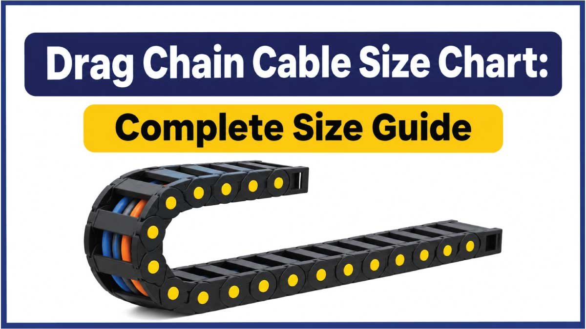
A drag chain cable is a specially designed flexible electrical cable used in machinery and automation systems where cables move repeatedly during operation. It is installed inside a cable carrier, also called an energy chain, cable track, or drag chain, which guides and protects cables as machine components move.
Unlike ordinary fixed-installation cables, drag chain cables are manufactured to withstand repeated bending, flexing, vibration, and mechanical stress. Their conductor strands, insulation, internal construction, and outer jackets are designed for continuous movement.
Common applications include:
- CNC machining centers and milling machines.
- Industrial robots and robotic arms.
- Automated assembly lines.
- Packaging and processing machinery.
- Conveyor systems and material-handling equipment.
- Electrical control cabinets with moving connections.
- Gantry systems and automated storage equipment.
- Printing and textile machinery.
The correct cable size depends on both electrical requirements and mechanical operating conditions. A cable may have sufficient electrical capacity but still fail prematurely if it is not designed for continuous-flex applications.
Drag Chain Cable Size Chart
Drag chain cables are available in different conductor cross-sectional areas, commonly expressed in square millimeters (mm²) or American Wire Gauge (AWG). The appropriate size depends on current requirements, voltage drop, cable length, conductor material, installation conditions, and manufacturer specifications.
The following chart provides a reference for common conductor sizes used in industrial flexible cable applications.
| AWG Size | Cross-Sectional Area (mm²) | Typical Identification |
|---|---|---|
| 24 AWG | 0.205 | Small signal conductors |
| 22 AWG | 0.326 | Control and signal circuits |
| 20 AWG | 0.518 | Control wiring |
| 18 AWG | 0.823 | Control and auxiliary circuits |
| 16 AWG | 1.31 | Control and light-duty power |
| 14 AWG | 2.08 | Power and control applications |
| 12 AWG | 3.31 | Industrial power circuits |
| 10 AWG | 5.26 | Higher-current power applications |
| 8 AWG | 8.37 | Larger power conductors |
| 6 AWG | 13.3 | Heavy-duty power applications |
| 4 AWG | 21.2 | Large power conductors |
| 2 AWG | 33.6 | High-power installations |
Important: These are nominal conductor cross-sectional area references, not ampacity ratings or universal drag chain cable recommendations. Actual current capacity must be determined from the specific cable datasheet, applicable electrical standards, operating temperature, conductor construction, and installation conditions.
How to Read the Drag Chain Cable Size Chart
The AWG column identifies the conductor gauge, while the cross-sectional area column shows the approximate conductive area in square millimeters.
For example:
- 24 AWG is commonly associated with small signal conductors.
- 20 AWG is used in various control and communication applications.
- 18 AWG is found in many low-power control circuits.
- 16 AWG and 14 AWG are available for larger control and power requirements.
- 12 AWG and 10 AWG are used in applications requiring larger conductor cross-sections.
A smaller AWG number indicates a larger conductor. For metric cable sizing, the opposite comparison does not apply because a larger mm² value represents a larger conductor.
Always check the manufacturer’s specifications before choosing a cable based on its nominal conductor size.
Drag Chain Cable Size by Application
Different industrial applications require different cable constructions and conductor sizes. The correct selection depends on the electrical load, number of conductors, movement profile, and surrounding environment.
CNC Machine Drag Chain Cable
CNC machines use drag chain cables to connect moving machine components with electrical power, control signals, and feedback systems.
Common requirements include:
- Continuous-flex conductor construction.
- Resistance to repeated bending.
- Suitable insulation and jacket materials.
- Protection against machining oils and coolants.
- Appropriate shielding for sensitive signals.
Power cables, encoder cables, motor cables, and control cables may all be installed in CNC cable carriers. Their conductor sizes should be selected individually according to their electrical functions.
Robotics Drag Chain Cable
Robotic systems require highly flexible cables because their movement may involve bending, rotation, and twisting.
Common requirements include:
- Fine-stranded or extra-fine-stranded conductors.
- Torsion-resistant construction where required.
- Abrasion-resistant jackets.
- Suitable shielding for signal integrity.
- Cable designs rated for the robot’s movement profile.
A standard drag chain cable is not automatically suitable for robotic twisting applications. Check whether the manufacturer’s specifications explicitly permit torsional movement.
Conveyor System Drag Chain Cable
Conveyor systems use flexible cables to connect moving equipment, sensors, motors, and control components.
The cable size depends on:
- Motor power requirements.
- Supply voltage.
- Circuit current.
- Cable length.
- Starting and operating conditions.
- Movement frequency.
Power cables generally require larger conductors than low-power sensor and control cables, but the exact sizes must be calculated for each circuit.
Industrial Automation Drag Chain Cable
Automated production systems commonly use separate cables for power, communication, control, and feedback.
Typical cable categories include:
- Power supply cables.
- Servo motor cables.
- Encoder cables.
- Sensor cables.
- Data transmission cables.
- Control cables.
Each cable must have suitable conductor dimensions, insulation, shielding, and mechanical flexibility for its intended function.
Types of Drag Chain Cables
Drag chain cables are available in several constructions depending on the electrical and mechanical requirements of the machinery.
Power Drag Chain Cables
Power drag chain cables supply electrical energy to motors, actuators, and moving machine components.
They are available in different conductor sizes and core configurations. The required conductor cross-section depends on current, voltage drop, temperature, cable length, and applicable electrical standards.
Control Drag Chain Cables
Control cables transmit electrical signals between machine components, controllers, switches, and automation equipment.
They generally contain multiple conductors and are available in different cross-sectional areas.
They are commonly used for:
- Limit switches.
- Control panels.
- Machine sensors.
- Automated equipment.
- Industrial control systems.
Shielded Drag Chain Cables
Shielded cables include a conductive protective layer designed to reduce electromagnetic interference.
They are useful for applications involving sensitive control signals, communication circuits, encoders, and variable-frequency drive equipment.
The shielding construction and termination method should follow the cable manufacturer’s instructions and the machine’s EMC requirements.
Servo Motor Drag Chain Cables
Servo cables connect servo drives to motors in automated motion-control systems.
They may include power conductors, protective earth conductors, and additional signal or feedback elements depending on their design.
These cables must be selected according to motor specifications, drive compatibility, movement requirements, and manufacturer recommendations.
Data and Communication Drag Chain Cables
Data cables carry communication signals between controllers, sensors, drives, and other industrial devices.
Common examples include Ethernet, fieldbus, and encoder cables.
Their selection depends on transmission requirements, shielding, impedance, cable construction, and the mechanical demands of the drag chain.
Drag Chain Cable Core Configuration Chart
Cable core configuration refers to the number of individual insulated conductors inside a cable. The correct number depends on the equipment connections and electrical circuit design.
| Core Configuration | General Description | Common Application |
|---|---|---|
| 2 Core | Two insulated conductors | Simple power and control circuits |
| 3 Core | Three insulated conductors | Single-phase or other three-conductor circuits |
| 4 Core | Four insulated conductors | Three-phase power and control applications |
| 5 Core | Five insulated conductors | Three-phase systems with additional conductors |
| 7 Core | Seven insulated conductors | Machine control systems |
| 12 Core | Twelve insulated conductors | Multi-signal control systems |
| 18 Core | Eighteen insulated conductors | Complex automation equipment |
| 25 Core | Twenty-five insulated conductors | Multiple control and signal circuits |
This table describes common configurations rather than fixed electrical assignments. The actual purpose of each conductor depends on the cable design and equipment wiring diagram.
For complicated installations, using several dedicated cables instead of one large multi-core cable may improve separation, flexibility, and maintenance.
Drag Chain Cable Size and Bending Radius
Bending radius is one of the most important factors when selecting a drag chain cable. It describes the minimum radius through which a cable can bend without exceeding its specified mechanical limits.
The cable manufacturer’s minimum dynamic bending radius must be compatible with the cable carrier’s bending radius.
A common way to express bending radius is as a multiple of the cable’s outside diameter (OD).
| Bend Radius Multiple | Calculation | Meaning |
|---|---|---|
| 5 × OD | 5 times cable diameter | Only where specifically permitted |
| 7.5 × OD | 7.5 times cable diameter | Example of a manufacturer-rated dynamic radius |
| 10 × OD | 10 times cable diameter | Larger bending allowance |
| 12.5 × OD | 12.5 times cable diameter | More generous bending allowance |
| 15 × OD | 15 times cable diameter | Larger radius requirement |
Example: If a cable has an outside diameter of 10 mm and its datasheet specifies a minimum dynamic bending radius of 7.5 × OD, the minimum radius is:
10 × 7.5 = 75 mm
The selected cable carrier must accommodate at least the required cable bending radius.
These multiples are illustrative calculation examples, not universal minimum ratings. Always use the exact dynamic bending radius specified for the selected cable.
Read Latest Guide:
Factors That Affect Drag Chain Cable Size
Choosing a suitable drag chain cable requires evaluating electrical performance and mechanical operating conditions together.
Current and Electrical Load
The conductor must carry the expected operating current without exceeding its permitted temperature.
Consider:
- Equipment power requirements.
- Supply voltage.
- Continuous and intermittent loads.
- Starting current where relevant.
- Conductor material.
- Applicable ampacity requirements.
Never select a conductor based only on its AWG or mm² designation.
Cable Length and Voltage Drop
Longer cable runs can increase voltage drop, particularly when the equipment draws substantial current.
Consider the complete electrical circuit length, conductor resistance, operating current, and acceptable voltage drop.
A larger conductor may be necessary when the cable run is long or voltage-drop limits are restrictive.
Travel Distance
Travel distance describes how far the moving machine component travels during operation.
Longer travel distances can increase mechanical stress and affect cable carrier selection. Cable construction must be suitable for the complete movement profile.
Operating Speed and Acceleration
High travel speeds and rapid acceleration place additional mechanical demands on drag chain cables.
The cable manufacturer should provide suitable operating limits for:
- Maximum travel speed.
- Acceleration.
- Dynamic bending radius.
- Expected flex cycles.
- Permitted mechanical loading.
Temperature and Environmental Conditions
Cable insulation and jacket materials must withstand the operating environment.
Consider exposure to:
- Heat and cold.
- Industrial oils.
- Coolants.
- Chemicals.
- Moisture.
- Abrasion.
- Dust and metal particles.
PUR, PVC, and TPE jackets have different properties. Select the material according to the actual environmental and mechanical requirements.
Read Latest Guide:
How to Choose the Correct Drag Chain Cable Size
Follow these steps to select an appropriate cable for an industrial moving application.
Step 1: Identify the Electrical Requirements
Determine the equipment voltage, operating current, power demand, and electrical function.
Identify whether the cable will supply power, transmit control signals, or carry communication data.
Step 2: Determine the Number of Conductors
Check the equipment wiring diagram to establish the required number of cores.
Include protective earth and any additional conductors required by the electrical design.
Step 3: Calculate the Conductor Cross-Section
Select an appropriate conductor size using the expected current, cable length, voltage drop, temperature, and applicable electrical requirements.
Verify the selected size against the manufacturer’s technical data.
Step 4: Check the Cable Outside Diameter
Measure or obtain the cable’s overall diameter from its datasheet.
This dimension is necessary when calculating the required cable carrier space and bend radius.
Step 5: Verify the Dynamic Bending Radius
Check the minimum dynamic bending radius specified by the cable manufacturer.
Choose a drag chain with a compatible or larger bending radius.
Step 6: Evaluate Movement Conditions
Check the travel distance, operating speed, acceleration, movement frequency, and expected service life.
Select a cable specifically rated for those conditions.
Step 7: Confirm Environmental Compatibility
Choose an insulation and jacket material that can withstand the actual operating environment.
For example, machinery exposed to cutting fluids may require a different jacket construction from equipment operating in a clean indoor environment.
Read Latest Guide:
Drag Chain Cable Installation Guidelines
Correct installation is just as important as selecting the correct cable size. Poor cable arrangement can cause twisting, abrasion, mechanical stress, and premature failure.
Maintain Proper Cable Spacing
Do not overcrowd the cable carrier. Allow enough space for cables to move freely during operation.
Some manufacturers recommend limiting the total carrier cross-sectional fill to approximately 80%, while other designs specify different limits. Follow the carrier and cable manufacturers’ instructions.
Arrange Cables Properly
Install cables in a balanced arrangement according to their diameters and weights.
Important practices include:
- Avoid crossing cables over one another.
- Prefer a single layer where practical.
- Use separators between different cable groups.
- Separate cables with different diameters or jacket materials where required.
- Prevent cables from twisting during movement.
Allow Free Cable Movement
Cables must move freely inside the bending section of the drag chain.
Do not tie cables together throughout the moving section. Use suitable fixation devices at the designated fixed and moving ends.
Provide Sufficient Cable Length
Allow appropriate cable reserve at both ends of the carrier.
Avoid excessive tension when the machine reaches its maximum travel position.
Inspect Cables Regularly
Periodically inspect the installation for:
- Jacket damage.
- Abrasion.
- Cable twisting.
- Unusual stretching.
- Overlapping cables.
- Loose fixation.
- Signs of overheating.
Replace damaged cables and investigate the cause of failure before returning the machinery to service.
Common Drag Chain Cable Sizing Mistakes
Avoid these common mistakes when designing or installing a cable carrier system.
Using Ordinary Flexible Cable
A flexible cable is not necessarily suitable for continuous drag chain movement. Choose a cable specifically rated for the intended dynamic application.
Ignoring Minimum Bending Radius
Using a carrier with an insufficient bending radius can increase conductor fatigue and jacket damage.
Choosing Wire Size Only by Amperage
Electrical capacity alone does not determine drag chain suitability. Mechanical flexibility, cable diameter, movement frequency, and environmental conditions are equally important.
Overfilling the Cable Carrier
Excessive filling can restrict cable movement and increase friction. Maintain the clearance required by the carrier manufacturer.
Ignoring Cable Weight
Heavy cables can affect the carrier’s load capacity and unsupported travel performance. Check the manufacturer’s carrier load specifications.
Mixing Power and Signal Cables Without Separation
Power cables can create electromagnetic interference that affects sensitive signal and communication circuits. Use appropriate separation and shielding arrangements.
Frequently Asked Questions About Drag Chain Cable Size
1. What size cable is used in a drag chain?
Drag chain cables are available in many conductor sizes, including 24 AWG, 18 AWG, 16 AWG, 14 AWG, 12 AWG, and larger metric cross-sections. The correct size depends on electrical load, cable length, voltage drop, and mechanical requirements.
2. What is the difference between a drag chain cable and a regular cable?
A drag chain cable is designed for repeated movement and continuous bending. Regular installation cables may not have the conductor construction, insulation, or jacket durability required for repeated dynamic movement.
3. What is the minimum bending radius of a drag chain cable?
The minimum bending radius depends on the cable construction and manufacturer specifications. It is commonly expressed as a multiple of the cable outside diameter. Always check the dynamic bending radius rather than using a fixed value for every cable.
4. Can I use ordinary flexible cable in a drag chain?
Not automatically. A flexible cable should only be used if its manufacturer specifically approves it for the intended drag chain application and operating conditions.
5. How much space should be left inside a drag chain?
The required clearance depends on the carrier design and cable manufacturer’s recommendations. Some installation guidelines limit total cross-sectional fill to 80%. Sufficient clearance must remain for unrestricted cable movement.
6. What jacket material is best for drag chain cables?
PUR is commonly selected for demanding abrasion and oil-exposure applications. PVC can suit less demanding environments, while TPE may be appropriate for applications requiring particular flexibility or temperature performance. The best material depends on the actual environment.
7. Do drag chain cables need shielding?
Not all drag chain cables require shielding. Shielding is useful where electromagnetic interference could affect sensitive control, encoder, or communication signals. Follow the machine’s EMC requirements.
8. How long do drag chain cables last?
Cable service life depends on bending radius, travel distance, speed, acceleration, temperature, installation quality, and cable construction. Manufacturers may specify expected flex cycles under defined test conditions, but there is no universal service-life figure.
9. Can multiple cables be installed in one drag chain?
Yes. Multiple power, control, and signal cables can share a carrier when its dimensions and load capacity are suitable. Proper spacing, cable separation, and weight distribution are important.
10. How do I calculate the correct drag chain size?
Start by identifying the cable diameters, bending-radius requirements, and number of cables. Calculate the required internal carrier height and width while allowing sufficient clearance. Then verify carrier load capacity, travel distance, and movement conditions against manufacturer specifications.
Conclusion
Selecting the correct drag chain cable size requires balancing electrical requirements with mechanical performance. Conductor cross-sectional area, current capacity, cable diameter, bending radius, travel distance, and environmental conditions all influence the final selection.
Use the drag chain cable size chart as a starting reference for common conductor sizes, but always verify electrical ratings and dynamic movement specifications using the cable manufacturer’s datasheet. Proper cable spacing, suitable bend radius, balanced weight distribution, and regular inspection can help improve reliability and reduce premature cable failures.