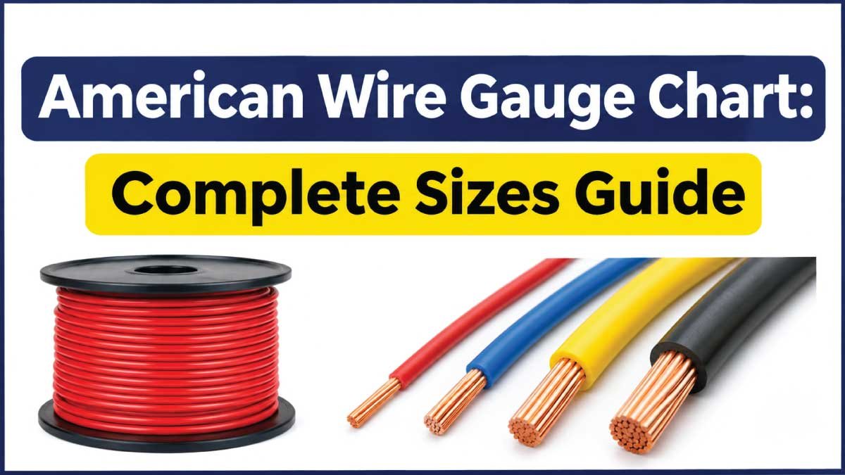
American Wire Gauge (AWG) is a standardized measurement system used to identify the diameter and cross-sectional area of electrical wires in the United States and other regions. It helps electricians, engineers, technicians, and homeowners select the correct wire for electrical installations, appliances, automotive systems, and industrial equipment.
The American Wire Gauge chart provides essential information about wire sizes, including diameter, cross-sectional area, and electrical resistance. Understanding these measurements makes it easier to compare different wire gauges and determine which size is suitable for a particular application.
One important detail about AWG is that smaller gauge numbers represent thicker wires, while larger numbers represent thinner wires. For example, 10 AWG wire is thicker than 14 AWG wire, and 4 AWG wire is much thicker than 10 AWG wire.
This guide explains standard AWG measurements, wire dimensions, resistance, ampacity considerations, common applications, and how to choose the correct wire size for different electrical requirements.
American Wire Gauge Chart
An American Wire Gauge chart helps identify the physical and electrical characteristics of different wire sizes. The most important measurements include wire diameter, cross-sectional area, and resistance.
The following chart covers commonly used AWG sizes, from large electrical conductors to small electronic wires. Dimensions are based on standard AWG relationships and approximate bare-conductor measurements.
Standard AWG Wire Size Chart
| AWG Size | Diameter (inches) | Diameter (mm) | Area (mm²) | Resistance (Ω/1000 ft) |
|---|---|---|---|---|
| 4/0 | 0.4600 | 11.684 | 107.2 | 0.0490 |
| 3/0 | 0.4096 | 10.404 | 85.0 | 0.0618 |
| 2/0 | 0.3648 | 9.266 | 67.4 | 0.0779 |
| 1/0 | 0.3249 | 8.251 | 53.5 | 0.0983 |
| 1 | 0.2893 | 7.348 | 42.4 | 0.1239 |
| 2 | 0.2576 | 6.544 | 33.6 | 0.1563 |
| 3 | 0.2294 | 5.827 | 26.7 | 0.1970 |
| 4 | 0.2043 | 5.189 | 21.2 | 0.2485 |
| 5 | 0.1819 | 4.621 | 16.8 | 0.3133 |
| 6 | 0.1620 | 4.115 | 13.3 | 0.3951 |
| 7 | 0.1443 | 3.665 | 10.5 | 0.4982 |
| 8 | 0.1285 | 3.264 | 8.37 | 0.6282 |
| 9 | 0.1144 | 2.906 | 6.63 | 0.7921 |
| 10 | 0.1019 | 2.588 | 5.26 | 0.9989 |
| 12 | 0.0808 | 2.053 | 3.31 | 1.588 |
| 14 | 0.0641 | 1.628 | 2.08 | 2.525 |
| 16 | 0.0508 | 1.291 | 1.31 | 4.016 |
| 18 | 0.0403 | 1.024 | 0.823 | 6.385 |
| 20 | 0.0320 | 0.812 | 0.518 | 10.15 |
| 22 | 0.0253 | 0.644 | 0.326 | 16.14 |
| 24 | 0.0201 | 0.511 | 0.205 | 25.67 |
| 26 | 0.0159 | 0.405 | 0.129 | 40.81 |
| 28 | 0.0126 | 0.321 | 0.0810 | 64.90 |
| 30 | 0.0100 | 0.255 | 0.0509 | 103.2 |
Note: Resistance values are approximate reference values for solid copper conductors at approximately 20°C. Actual resistance varies with conductor material, temperature, manufacturing tolerances, and construction.
How to Read an AWG Chart
Reading an AWG chart is straightforward once you understand the relationship between gauge numbers and wire dimensions.
Consider these examples:
- 10 AWG: A relatively thick wire commonly used in suitable branch circuits, appliances, and electrical equipment.
- 12 AWG: A common residential wiring size used in applications such as general-purpose 20-amp circuits where permitted.
- 14 AWG: A smaller conductor frequently used in suitable 15-amp residential circuits.
- 18 AWG: A thin wire commonly found in control circuits, electronics, and low-voltage equipment.
- 24 AWG: A very thin conductor often used in communication cables and electronic devices.
Remember that the AWG number describes the conductor size, not its insulation thickness or overall cable diameter.
Understanding American Wire Gauge Measurements
AWG measurements describe several important characteristics of electrical conductors. Each measurement provides different information about wire performance and suitability.
Wire Diameter
Wire diameter refers to the thickness of a conductor measured across its circular cross-section.
It is generally expressed in inches or millimeters.
For example:
- 10 AWG wire has a diameter of approximately 2.588 mm.
- 12 AWG wire has a diameter of approximately 2.053 mm.
- 14 AWG wire has a diameter of approximately 1.628 mm.
- 16 AWG wire has a diameter of approximately 1.291 mm.
A larger diameter generally provides more conductive material and lower electrical resistance when comparing conductors made from the same material.
Cross-Sectional Area
Cross-sectional area measures the amount of conductive material inside a wire.
It is usually expressed in square millimeters (mm²) or circular mils (kcmil).
This measurement is particularly important when comparing AWG wire with metric wire sizes.
For example, 12 AWG copper wire has a nominal cross-sectional area of approximately 3.31 mm², while 10 AWG has approximately 5.26 mm².
A greater cross-sectional area generally allows a conductor to carry more current under otherwise comparable conditions.
Electrical Resistance
Electrical resistance describes how strongly a conductor opposes the flow of electric current.
It is commonly measured in ohms (Ω).
Thinner wires generally have higher resistance per unit length than thicker wires made from the same material.
For example, 14 AWG copper wire has approximately 2.525 ohms of resistance per 1,000 feet, while 10 AWG has approximately 0.9989 ohms per 1,000 feet.
Lower resistance can help reduce voltage drop and electrical energy losses.
American Wire Gauge Size Comparison
Different AWG sizes are designed for different electrical requirements. Comparing common wire sizes helps identify their relative dimensions and typical uses.
Common AWG Wire Comparison Chart
| AWG Size | Diameter (mm) | Area (mm²) | General Applications |
|---|---|---|---|
| 8 AWG | 3.264 | 8.37 | Suitable power equipment and electrical installations |
| 10 AWG | 2.588 | 5.26 | Appliances and selected branch circuits |
| 12 AWG | 2.053 | 3.31 | General-purpose residential circuits |
| 14 AWG | 1.628 | 2.08 | Lighting and suitable residential circuits |
| 16 AWG | 1.291 | 1.31 | Automotive and electronic wiring |
| 18 AWG | 1.024 | 0.823 | Control wiring and low-voltage devices |
| 20 AWG | 0.812 | 0.518 | Electronic equipment and signal wiring |
| 22 AWG | 0.644 | 0.326 | Sensors and communication equipment |
| 24 AWG | 0.511 | 0.205 | Data and communication cables |
These are general application examples, not universal current ratings. Actual suitability depends on installation conditions, insulation ratings, applicable electrical codes, and equipment requirements.
Thick Wire vs. Thin Wire
The main difference between thick and thin electrical wires is their cross-sectional area and electrical resistance.
Thick wires:
- Have larger cross-sectional areas.
- Generally have lower electrical resistance.
- Can support higher current capacities under comparable conditions.
- Are commonly used in power distribution and high-current applications.
- May require larger terminals and connectors.
Thin wires:
- Have smaller cross-sectional areas.
- Generally have higher electrical resistance.
- Are commonly used in electronics and signal applications.
- Require careful consideration of current and voltage drop.
- Are often easier to route through compact equipment.
Choosing between thick and thin wires requires considering the actual electrical load rather than selecting a wire based only on its physical appearance.
How the AWG Numbering System Works
The American Wire Gauge system follows a reverse numbering relationship. As the gauge number increases, the conductor diameter decreases.
For example, 8 AWG wire is thicker than 12 AWG, and 12 AWG is thicker than 16 AWG.
This numbering system can initially seem confusing because many other measurement systems use larger numbers to represent larger dimensions.
AWG Numbering Relationship
The AWG system follows a standardized mathematical relationship between successive wire sizes.
Each three-gauge-number increase reduces the conductor diameter by approximately half.
For example:
- 10 AWG is thicker than 13 AWG.
- 13 AWG is thicker than 16 AWG.
- 16 AWG is thicker than 19 AWG.
The diameter ratio between adjacent gauge sizes is approximately 1.1229.
This consistent relationship makes it possible to calculate wire dimensions for different AWG sizes.
What Do 1/0, 2/0, 3/0, and 4/0 Mean?
Large electrical conductors use a special notation called aught sizes.
These sizes are written as 1/0, 2/0, 3/0, and 4/0 rather than using ordinary whole numbers.
The relationship is:
| AWG Designation | Common Name | Diameter (mm) |
|---|---|---|
| 1/0 | One aught | 8.251 |
| 2/0 | Two aught | 9.266 |
| 3/0 | Three aught | 10.404 |
| 4/0 | Four aught | 11.684 |
The higher the aught number, the thicker the conductor.
These large sizes are commonly associated with electrical services, battery connections, industrial equipment, and other applications requiring substantial conductors.
American Wire Gauge Ampacity Chart: Understanding Current Capacity
Ampacity refers to the maximum current a conductor can carry continuously under specified conditions without exceeding its permitted temperature rating.
Although AWG size is an important factor in determining ampacity, the gauge number alone does not establish a safe current limit.
Two wires with the same AWG size may have different allowable current capacities because of their insulation, installation methods, ambient temperatures, and surrounding conditions.
Factors That Affect Wire Ampacity
Several factors influence the current-carrying capacity of an electrical conductor.
1. Conductor Material
Copper and aluminum have different electrical properties.
Copper generally has lower electrical resistance than aluminum of the same cross-sectional area. Therefore, aluminum conductors often require a larger size to achieve comparable electrical performance.
2. Insulation Temperature Rating
Wire insulation is designed to operate within a specified temperature range.
Common insulation temperature ratings include 60°C, 75°C, and 90°C. However, the allowable ampacity must be determined using the applicable conductor and equipment ratings.
3. Ambient Temperature
High surrounding temperatures can reduce the amount of current a conductor can safely carry.
Electrical installations in hot environments may require ampacity adjustments.
4. Number of Current-Carrying Conductors
When several current-carrying conductors are installed together in a conduit or cable assembly, heat can build up.
Applicable electrical codes may require ampacity adjustments depending on the number of conductors and installation conditions.
5. Installation Method
The way a wire is installed also affects its ability to release heat.
Conductors installed in open air may have different thermal conditions from conductors installed inside conduit, cable assemblies, or enclosed spaces.
Why a Universal AWG Ampacity Chart Can Be Misleading
A simple chart showing one current rating for each AWG size may not accurately represent every electrical installation.
For example, a particular copper conductor may have different allowable ampacities depending on its insulation temperature rating and the applicable electrical code.
Therefore, always check the relevant ampacity tables, correction factors, equipment limitations, and local regulations before selecting a wire for a power circuit.
Copper vs. Aluminum AWG Wire
Copper and aluminum are two widely used materials for electrical conductors. Both can be manufactured in different AWG sizes, but their electrical and physical properties are different.
Copper Wire Characteristics
Copper is commonly used in residential, commercial, automotive, and industrial electrical installations.
Its main advantages include:
- High electrical conductivity.
- Lower resistance than aluminum of the same cross-sectional area.
- Good mechanical strength.
- Reliable connections when properly installed.
- Compatibility with many electrical terminals and connectors.
Copper is often preferred for smaller electrical wiring and applications where space is limited.
Read Latest Guide:
Aluminum Wire Characteristics
Aluminum is also used in electrical distribution and larger power installations.
Its advantages include:
- Lower weight than copper.
- Often lower material cost.
- Good conductivity relative to its weight.
- Suitability for certain large electrical conductors.
- Use in overhead distribution and approved building wiring applications.
However, aluminum wiring requires compatible terminals, connectors, and installation practices.
Copper vs. Aluminum Comparison
| Characteristic | Copper Wire | Aluminum Wire |
|---|---|---|
| Electrical conductivity | Higher | Lower |
| Weight | Heavier | Lighter |
| Resistance at equal area | Lower | Higher |
| Mechanical strength | Generally higher | Generally lower |
| Typical applications | Residential, automotive, industrial | Power distribution, service conductors |
| Connection requirements | Standard compatible terminals | Aluminum-rated connections where required |
Copper and aluminum conductors should not be treated as interchangeable simply because they have the same AWG designation.
Always use the conductor size, terminal rating, and installation method specified for the electrical application.
Read Latest Guide:
AWG to Metric Wire Size Conversion Chart
Many countries use metric measurements to identify electrical conductor sizes. As a result, converting AWG measurements into square millimeters is useful when working with international equipment and electrical specifications.
The following chart provides approximate conversions for commonly used AWG sizes.
AWG to Square Millimeter Conversion
| AWG Size | Cross-Sectional Area (mm²) | Approximate Metric Comparison |
|---|---|---|
| 4/0 | 107.2 | 107 mm² |
| 2/0 | 67.4 | 70 mm² |
| 1/0 | 53.5 | 50 mm² |
| 2 | 33.6 | 35 mm² |
| 4 | 21.2 | 25 mm² |
| 6 | 13.3 | 16 mm² |
| 8 | 8.37 | 10 mm² |
| 10 | 5.26 | 6 mm² |
| 12 | 3.31 | 4 mm² |
| 14 | 2.08 | 2.5 mm² |
| 16 | 1.31 | 1.5 mm² |
| 18 | 0.823 | 1 mm² |
| 20 | 0.518 | 0.5 mm² |
| 22 | 0.326 | 0.35 mm² |
| 24 | 0.205 | 0.2 mm² |
Important: Metric comparisons are approximate and do not establish direct interchangeability. Metric conductor sizes are separate standardized nominal sizes.
Read Latest Guide:
How to Convert AWG to Millimeters
AWG wire diameter can be calculated using a mathematical formula based on the gauge number.
The standard relationship is:
Diameter (inches) = 0.005 × 92^((36 − AWG) / 39)
To convert inches into millimeters, multiply the diameter by 25.4.
For example, 12 AWG wire has a diameter of approximately 0.0808 inches.
0.0808 × 25.4 = 2.053 mm
This calculation provides the nominal conductor diameter and does not include insulation.
Common Applications of American Wire Gauge Sizes
Different wire gauges are used across residential, automotive, industrial, and electronic systems.
Understanding common applications helps narrow down the appropriate wire size before checking the specific electrical requirements.
Residential Electrical Wiring
AWG sizes are widely used in residential electrical systems in the United States.
Common examples include:
- 14 AWG for suitable 15-amp branch circuits.
- 12 AWG for suitable 20-amp branch circuits.
- 10 AWG for certain higher-load branch circuits.
- Larger conductors for electrical services and distribution equipment.
These examples assume appropriate copper conductors and compliant installation conditions. Circuit protection, conductor material, terminal ratings, and local code requirements must always be considered.
Automotive Wiring
Automotive electrical systems use a range of AWG sizes depending on current demand, circuit length, and operating conditions.
Typical applications include:
- Battery connections.
- Starter motor circuits.
- Alternator wiring.
- Lighting systems.
- Electronic accessories.
- Sensor and control circuits.
High-current automotive circuits may require thicker conductors to minimize voltage drop and prevent excessive heating.
Industrial Electrical Systems
Industrial installations use different AWG sizes for power distribution, machinery, motors, control panels, and electrical equipment.
Large conductors are commonly used for power circuits, while smaller wires are used for control signals and instrumentation.
Wire selection depends on motor current, circuit protection, installation conditions, and applicable electrical standards.
Electronic and Communication Equipment
Smaller AWG sizes are frequently used in electronic devices and communication systems.
Examples include:
- 18 AWG for selected control and power connections.
- 22 AWG for certain signal and sensor circuits.
- 24 AWG for communication and data cables.
- 26–30 AWG for compact electronic connections.
The appropriate size depends on the electrical load, signal requirements, cable construction, and manufacturer specifications.
How to Choose the Correct AWG Wire Size
Choosing the correct AWG wire size requires more than matching a gauge number to an electrical device.
The conductor must safely handle the expected current while maintaining acceptable voltage drop and meeting installation requirements.
1. Determine the Electrical Load
Start by identifying the current required by the connected equipment.
The load current is usually provided on the equipment nameplate or technical documentation.
For a basic single-phase electrical load, current can be estimated using:
Current (A) = Power (W) ÷ Voltage (V)
For example, a 1,200-watt device operating at 120 volts draws approximately 10 amperes under the assumed conditions.
This calculation provides an initial estimate, not a complete wire-sizing decision.
2. Identify the Wire Material
Determine whether the application requires copper or aluminum conductors.
The two materials have different resistance characteristics and installation requirements.
Never select a replacement conductor based only on matching the original wire’s AWG number.
3. Measure the Circuit Length
Longer electrical circuits experience greater voltage drop.
This is particularly important for automotive wiring, battery connections, outdoor equipment, and low-voltage installations.
A larger conductor may be necessary to maintain acceptable voltage at the connected equipment.
4. Check Insulation and Temperature Ratings
Confirm that the insulation is suitable for the installation environment.
Consider:
- Operating temperature.
- Exposure to moisture.
- Chemical exposure.
- Mechanical protection.
- Indoor or outdoor installation.
- Applicable electrical ratings.
5. Verify Electrical Code Requirements
Use the applicable electrical code and manufacturer documentation to confirm the final wire size.
For installations in the United States, the National Electrical Code (NEC) provides requirements for conductor ampacity, overcurrent protection, and installation practices.
Other countries have their own electrical standards and regulations.
Common Mistakes When Using an AWG Chart
Even experienced users can make wire-sizing mistakes when they focus on only one measurement.
Avoid these common problems:
- Choosing the wrong gauge: Remember that a smaller AWG number represents a thicker conductor.
- Ignoring voltage drop: Long circuits may require larger conductors than short circuits.
- Confusing conductor and cable diameter: AWG describes the conductor, not the complete insulated cable.
- Ignoring conductor material: Copper and aluminum require different considerations.
- Assuming ampacity is universal: Installation conditions and temperature ratings affect allowable current.
- Using incompatible terminals: Connectors must be approved for the conductor material and size.
- Ignoring local electrical codes: A wire that appears suitable may not meet the applicable installation requirements.
Carefully checking these factors helps prevent overheating, excessive voltage drop, connection problems, and electrical hazards.
Frequently Asked Questions About American Wire Gauge
1. What Does AWG Stand For?
AWG stands for American Wire Gauge. It is a standardized system used to identify the diameter of electrical conductors. It is commonly used for copper and aluminum wiring in electrical, automotive, and electronic applications.
2. Does a Higher AWG Number Mean Thicker Wire?
No. A higher AWG number means a thinner conductor. For example, 16 AWG wire is thinner than 12 AWG wire. As the gauge number decreases, the wire diameter and cross-sectional area increase.
3. What Is the Most Common AWG Wire Size?
Commonly encountered residential wire sizes include 14 AWG, 12 AWG, and 10 AWG. These sizes are used in different electrical applications depending on the required current, conductor material, and installation conditions.
4. What Is the Difference Between 12 AWG and 14 AWG Wire?
12 AWG wire has a larger diameter and cross-sectional area than 14 AWG wire. It also has lower electrical resistance per unit length. Both are commonly used in residential electrical installations, but their permitted applications and circuit protection requirements differ.
5. How Many Millimeters Is 10 AWG Wire?
10 AWG wire has a nominal conductor diameter of approximately 2.588 millimeters and a cross-sectional area of approximately 5.26 square millimeters. These measurements refer to the bare conductor, excluding insulation.
6. What Is 12 AWG Wire in Square Millimeters?
12 AWG copper wire has a nominal cross-sectional area of approximately 3.31 mm². Its conductor diameter is approximately 2.053 mm.
7. Is AWG the Same as SWG?
No. AWG and SWG (Standard Wire Gauge) are different wire measurement systems. Their dimensions are not identical, even when they use the same gauge number. Always identify which measurement standard is being used before comparing wires.
8. Does Wire Length Affect AWG Selection?
Yes. Longer wire runs increase electrical resistance and voltage drop. Depending on the load and allowable voltage drop, a larger conductor may be necessary for a long circuit than for a shorter circuit carrying the same current.
9. Can Copper and Aluminum Wires Use the Same AWG Size?
Both materials can use AWG designations, but they do not have identical electrical performance. Aluminum has higher resistance than copper at the same cross-sectional area. Appropriate conductor sizing and compatible connectors are essential when using aluminum wiring.
10. How Do I Know Which AWG Wire to Use?
Determine the load current, circuit length, conductor material, insulation rating, installation conditions, and applicable electrical code requirements. Then verify the appropriate conductor size using approved ampacity and voltage-drop calculations.
Conclusion
The American Wire Gauge chart is an essential reference for understanding electrical wire dimensions and selecting suitable conductors. It provides important information about wire diameter, cross-sectional area, and electrical resistance.
The most important rule to remember is that lower AWG numbers indicate thicker wires, while higher numbers indicate thinner wires. However, choosing the correct conductor requires considering current capacity, voltage drop, wire material, insulation ratings, and installation conditions.
Whether you are working with residential wiring, automotive electrical systems, industrial equipment, or electronics, understanding AWG measurements helps you make better wire-sizing decisions. Always verify the final selection against applicable electrical codes and manufacturer specifications to ensure a safe and reliable installation.