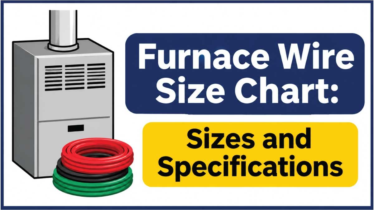
Choosing the correct wire size for a furnace is important for electrical safety, reliable operation, and proper equipment performance. An undersized conductor can overheat, cause voltage drop, and create a fire hazard. Incorrect circuit protection can also damage electrical components or leave the installation inadequately protected.
Furnaces are available in different types, including natural gas furnaces, propane furnaces, oil furnaces, and electric furnaces. Their electrical requirements are not the same. A gas furnace generally uses electricity for its control board, inducer motor, and blower motor, while an electric furnace uses electricity to power heating elements that can require substantially larger conductors and circuit breakers.
This guide explains common furnace wire sizes, AWG measurements, breaker ratings, thermostat wiring, electrical specifications, and the factors to consider when selecting conductors.
Furnace Wire Size Chart
The required wire size depends primarily on the furnace type, electrical load, nameplate specifications, and installation conditions.
Gas Furnace Wire Size Chart
Most residential gas furnaces operate on a 115–120V electrical supply. Their electrical requirements are generally much lower than those of electric furnaces.
| Gas Furnace Electrical Requirement | Typical Copper Wire Size | Common Circuit Breaker Reference |
|---|---|---|
| Small gas furnace | 14 AWG | 15A |
| Medium gas furnace | 14 AWG | 15A |
| Larger gas furnace | 12 AWG | 20A |
| High-electrical-load gas furnace | 12 AWG | 20A |
These are general references, not universal specifications. The furnace nameplate and installation manual determine the required minimum conductor size and maximum overcurrent protection.
Electric Furnace Wire Size Chart
Electric furnaces use resistance heating elements, which can require considerably more electrical current than gas furnace controls and blower motors.
The following table provides preliminary copper-wire references for common branch-circuit ratings.
| Circuit Rating | General Copper Wire Reference | Typical Application |
|---|---|---|
| 15A | 14 AWG | Small electrical loads |
| 20A | 12 AWG | Smaller equipment circuits |
| 30A | 10 AWG | Moderate electrical loads |
| 40A | 8 AWG | Larger heating circuits |
| 50A | 6 AWG | Higher-current heating circuits |
| 60A | 6 AWG | Larger electrical loads |
| 70A | 4 AWG | High-current equipment |
| 80A | 4 AWG | Larger electric heating circuits |
| 100A | 3 AWG | High-capacity electrical equipment |
Important: This is a general reference based on common copper branch-circuit sizing practices, not a furnace-specific installation chart. Actual conductor ampacity depends on insulation rating, terminal temperature limitations, installation method, ambient temperature, and applicable electrical codes. Electric furnaces may also require multiple circuits.
Always use the equipment’s MCA, MOCP, heater-kit specifications, and installation instructions before selecting a conductor or breaker.
Understanding Furnace Wire Sizes
Furnace conductors are commonly identified using the American Wire Gauge (AWG) system. AWG indicates the physical thickness of an electrical conductor.
A smaller AWG number represents a thicker conductor, while a larger number represents a thinner conductor.
For example, 10 AWG wire is thicker than 12 AWG wire. A thicker conductor generally has lower electrical resistance and can carry more current under comparable installation conditions.
Common AWG Wire Size Chart
| Wire Gauge | Approximate Bare Conductor Diameter | Common Applications |
|---|---|---|
| 18 AWG | 1.02 mm | Thermostat and control wiring |
| 16 AWG | 1.29 mm | Low-voltage control applications |
| 14 AWG | 1.63 mm | Smaller furnace power circuits |
| 12 AWG | 2.05 mm | Higher-load furnace circuits |
| 10 AWG | 2.59 mm | Electric heating circuits |
| 8 AWG | 3.26 mm | Larger heating equipment |
| 6 AWG | 4.11 mm | High-current circuits |
| 4 AWG | 5.19 mm | Large electrical equipment |
The dimensions refer to bare copper conductors, not the outside diameter of insulated cable.
Why Correct Wire Gauge Matters
Selecting the correct conductor helps prevent overheating and excessive voltage drop. Furnaces contain motors, electronic control boards, ignition systems, and other components that require a suitable electrical supply.
An undersized conductor can develop excessive heat when carrying current. Long cable runs can also create voltage drop, potentially affecting equipment performance.
A properly sized conductor must satisfy the equipment’s electrical requirements and applicable electrical-code ampacity rules.
Gas Furnace vs. Electric Furnace Wiring Requirements
Understanding the difference between gas and electric furnace wiring is essential because their electrical loads can be very different.
Gas Furnace Wiring
A gas furnace burns natural gas or propane to generate heat. Electricity is mainly used to operate its electrical and control components.
These commonly include:
- Blower motor
- Inducer motor
- Electronic ignition system
- Furnace control board
- Safety switches and sensors
Many residential gas furnaces operate on a 115–120V supply and use a 15A or 20A branch circuit, depending on the model.
For example, a manufacturer installation table for certain gas furnaces specifies 14 AWG copper wire with a 15A maximum circuit breaker for several models. Larger models in the same product family may specify 12 AWG wire and a 20A breaker.
This demonstrates why the equipment’s electrical data matters more than its heating capacity alone.
Electric Furnace Wiring
An electric furnace uses resistance heating elements to generate heat. These elements can draw substantial current and may require 208V, 240V, or another rated electrical supply.
Unlike a typical gas furnace, an electric furnace may require:
- Larger branch-circuit conductors
- Higher-rated circuit breakers
- Multiple electrical circuits
- Dedicated heater-kit wiring
- Specific grounding and disconnect arrangements
The correct wire size depends on the heater’s kilowatt rating, voltage, circuit configuration, and manufacturer specifications.
Gas vs. Electric Furnace Comparison
| Feature | Gas Furnace | Electric Furnace |
|---|---|---|
| Primary heat source | Natural gas or propane | Electrical resistance elements |
| Common supply | 115–120V | 208–240V or model-specific |
| Electrical load | Usually relatively low | Often substantially higher |
| Common wire references | 14–12 AWG | 12–4 AWG or larger, depending on load |
| Circuit protection | Often 15–20A | Model-specific, often higher |
| Heating elements | Gas burner | Electric resistance elements |
These comparisons describe common residential equipment, not every furnace configuration.
Furnace Wire Size by Heating Capacity
Furnace capacity is often measured in BTU per hour (BTU/h). Common residential gas furnace sizes include 40,000, 60,000, 80,000, 100,000, and 120,000 BTU/h.
However, BTU input does not directly determine electrical wire size. A gas furnace’s electrical load depends on its motors, controls, and accessories.
40,000 BTU Furnace Wire Size
A 40,000 BTU gas furnace is commonly used in smaller residential applications.
Some models specify a 115–120V supply, 14 AWG copper conductors, and a 15A circuit breaker.
The actual requirement depends on the blower motor, control components, and manufacturer specifications.
60,000 BTU Furnace Wire Size
A 60,000 BTU gas furnace is used in small to medium-sized homes and residential spaces.
Many models have relatively modest electrical requirements. A 14 AWG copper conductor may be specified for some units, although other models may require a different size.
Check the nameplate and installation manual before selecting the branch circuit.
80,000 BTU Furnace Wire Size
An 80,000 BTU furnace is a common residential heating system.
Certain models use 14 AWG copper wire and a 15A circuit, while higher-electrical-load configurations may require 12 AWG and 20A protection.
The heating capacity alone is not enough to determine the correct conductor.
100,000 BTU Furnace Wire Size
A 100,000 BTU gas furnace is commonly used in larger residential spaces.
Some models specify 12 AWG copper conductors and a 20A circuit breaker, while others may have lower electrical requirements.
Always check the equipment’s maximum current, minimum circuit ampacity, and manufacturer wiring instructions.
120,000 BTU Furnace Wire Size
A 120,000 BTU furnace is generally designed for larger residential or commercial heating applications.
Depending on the blower motor and equipment design, the electrical circuit may require 12 AWG or another specified conductor size.
Do not assume that a 120,000 BTU gas furnace requires the same electrical circuit as a 120,000 BTU electric heating system.
Understanding MCA and MOCP
Some furnace and electric heater installations provide two important electrical specifications: Minimum Circuit Ampacity (MCA) and Maximum Overcurrent Protection (MOCP).
These values help determine the conductor and circuit protection requirements.
Minimum Circuit Ampacity (MCA)
MCA identifies the minimum required ampacity of the conductors supplying the equipment.
The selected conductor must have sufficient allowable ampacity after applying relevant electrical-code adjustments and corrections.
For example, if an electric heating unit specifies an MCA of 30A, the selected conductors must have an allowable ampacity of at least 30A under the actual installation conditions.
MCA is not necessarily the same as the equipment’s normal operating current.
Maximum Overcurrent Protection (MOCP)
MOCP identifies the maximum permitted rating of the fuse or circuit breaker protecting the equipment.
For example, if a heater specifies a maximum overcurrent protection rating of 40A, the selected breaker or fuse must not exceed that limit.
The manufacturer may also specify the permitted type of circuit protection.
MCA vs. MOCP Comparison
| Electrical Specification | Meaning | Main Purpose |
|---|---|---|
| MCA | Minimum Circuit Ampacity | Determines minimum conductor ampacity |
| MOCP | Maximum Overcurrent Protection | Limits the breaker or fuse rating |
| Rated Voltage | Required electrical supply | Confirms supply compatibility |
| Phase | Single-phase or three-phase | Identifies the power configuration |
| Frequency | Usually 50Hz or 60Hz | Confirms electrical compatibility |
MCA and MOCP have different purposes. Do not use the breaker rating alone to determine conductor size.
Also Read:
Furnace Thermostat Wire Size Chart
Thermostat wiring is different from the main furnace power supply. It carries low-voltage control signals between the thermostat and furnace control board.
Many conventional residential systems use 18 AWG thermostat wire.
Thermostat Wire Gauge Chart
| Thermostat Wire Gauge | Approximate Diameter | Common Application |
|---|---|---|
| 18 AWG | 1.02 mm | Standard thermostat wiring |
| 20 AWG | 0.81 mm | Certain low-voltage control applications |
| 22 AWG | 0.64 mm | Some control and signaling applications |
| 24 AWG | 0.51 mm | Specialized low-current control wiring |
The appropriate thermostat wire depends on the system’s control requirements, wire length, number of conductors, and manufacturer instructions.
Common Thermostat Wire Counts
| Wire Configuration | Common Purpose |
|---|---|
| 2-wire | Basic heating control |
| 3-wire | Certain heating and fan-control systems |
| 4-wire | Common heating and cooling controls |
| 5-wire | Heating, cooling, fan, and common connections |
| 7-wire or more | Multi-stage and advanced HVAC controls |
Wire colors are commonly used to identify thermostat terminals, but color conventions are not universal. Always follow the furnace wiring diagram.
Also Read:
Furnace Wire Types and Their Applications
Selecting the correct conductor material and insulation is just as important as choosing the correct gauge.
Copper Wire
Copper is widely used for furnace electrical circuits because it has good conductivity and is commonly specified by manufacturers.
Many furnace installation manuals specify copper conductors for field wiring. Do not substitute aluminum conductors unless the equipment terminals and manufacturer instructions explicitly permit them.
THHN and THWN-2 Wire
THHN and THWN-2 are common insulation designations for building wire.
- THHN: Thermoplastic high-heat-resistant nylon-coated wire.
- THWN-2: Thermoplastic heat- and water-resistant wire rated for wet or dry locations.
These conductors are generally installed using an approved raceway or wiring method. Their suitability depends on the installation environment and applicable electrical-code requirements.
NM-B Cable
NM-B cable is commonly used for certain indoor residential branch circuits.
It contains insulated conductors and a grounding conductor inside an outer jacket. However, it is not suitable for every furnace installation, particularly in locations where exposure to moisture or physical damage makes another wiring method necessary.
Check the furnace manual and local code before using NM-B.
High-Temperature Internal Furnace Wiring
Internal furnace wiring may require insulation designed to withstand elevated temperatures.
Replacement internal conductors must match the manufacturer’s specified wire type, temperature rating, and electrical characteristics.
Do not replace high-temperature internal wiring with ordinary building wire unless the manufacturer explicitly permits it.
Also Read:
Factors That Affect Furnace Wire Selection
Several conditions can influence the final conductor size.
1. Furnace Type
Gas and electric furnaces have different electrical requirements.
A gas furnace generally powers motors and electronic controls, while an electric furnace powers resistance heating elements that can draw much more current.
Identify the equipment type before selecting a conductor.
2. Electrical Voltage
Furnaces may operate at 115–120V, 208V, 230–240V, or another specified voltage.
The electrical supply must match the furnace nameplate. Never assume that a furnace can operate on a different voltage simply because its physical connections appear compatible.
3. Cable Length
Longer conductor runs increase resistance and can create voltage drop.
If the circuit distance is substantial, a larger conductor may be necessary to maintain an acceptable voltage at the furnace.
Some manufacturers provide maximum wire lengths based on a specified voltage-drop limit.
4. Ambient Temperature
High ambient temperatures can reduce the allowable ampacity of conductors.
This is important when wiring is installed near heating equipment, in warm mechanical spaces, or in locations exposed to elevated temperatures.
5. Auxiliary Equipment
A furnace may have accessories such as humidifiers, electronic air cleaners, condensate pumps, or additional control equipment.
If accessories share a circuit, their electrical loads must be considered according to the furnace instructions and applicable electrical code.
6. Electric Heating Capacity
Electric furnace requirements depend heavily on the installed heating-element capacity.
A larger kilowatt heating package may require multiple circuits and larger conductors. Always check the heater-kit documentation rather than estimating wire size from furnace dimensions or airflow capacity.
How to Choose the Correct Furnace Wire Size
Follow these steps when determining the correct conductor and circuit protection.
Step 1: Identify the Furnace Type
Determine whether the equipment is gas, propane, oil, or electric.
Also identify whether the furnace includes electric auxiliary heating or additional heater kits.
Step 2: Read the Equipment Nameplate
Locate the furnace electrical data label and record:
- Rated voltage
- Phase and frequency
- Maximum unit current
- Minimum circuit ampacity, if provided
- Maximum fuse or breaker rating
- Manufacturer model number
Use the electrical information for the exact equipment.
Step 3: Check the Installation Manual
Review the electrical installation section for minimum conductor size, approved wire type, breaker requirements, and connection instructions.
For electric furnaces, check the specific heater-kit electrical tables.
Step 4: Measure the Circuit Distance
Measure the conductor route from the electrical panel to the furnace.
For longer distances, calculate voltage drop and determine whether a larger conductor is necessary.
Step 5: Verify Conductor Ampacity
Confirm that the selected conductor meets the equipment’s required ampacity after considering:
- Conductor material
- Insulation temperature rating
- Terminal temperature limitations
- Ambient-temperature correction
- Conductor-count adjustment
- Installation method
Step 6: Select the Correct Circuit Protection
Use the manufacturer’s maximum permitted overcurrent protection rating and follow the applicable electrical code.
Do not install a larger breaker to compensate for an undersized conductor.
Step 7: Check Grounding and Connections
Confirm the required equipment grounding conductor, disconnecting means, and terminal connections.
All electrical work should be performed by a qualified professional.
Common Furnace Wiring Mistakes
Incorrect furnace wiring can create safety hazards and damage equipment.
Choosing Wire Based Only on BTU Capacity
Furnace heating capacity does not directly determine electrical requirements. Always check the nameplate and installation manual.
Using the Same Wire Size for Gas and Electric Furnaces
Gas furnaces generally have lower electrical loads than electric furnaces. Electric heating elements may require much larger conductors and separate circuits.
Ignoring Electric Heater Kits
An electric furnace or auxiliary heater package may require multiple branch circuits. Failing to account for these loads can result in an inadequate electrical installation.
Installing an Oversized Breaker
The breaker must not exceed the equipment’s specified maximum overcurrent protection rating.
Using Incorrect Thermostat Wiring
Thermostat wiring must match the control-board terminal arrangement. Incorrect connections can cause improper operation or damage low-voltage components.
Ignoring Wire Temperature Ratings
Internal furnace wiring can be exposed to elevated temperatures. Replacement conductors must meet the manufacturer’s specified insulation and temperature requirements.
Skipping Equipment Grounding
Proper grounding provides an important fault-current path. Never omit the grounding conductor or use it as a normal current-carrying conductor.
Frequently Asked Questions
What size wire does a gas furnace need?
Many residential gas furnaces use 14 AWG copper wire on a 15A circuit. Some models require 12 AWG wire and 20A protection. Always verify the exact nameplate and installation manual.
What size wire is needed for an electric furnace?
Electric furnace wire size depends on its voltage, heating-element kilowatt rating, MCA, MOCP, and circuit arrangement. Some systems require 10 AWG, 8 AWG, 6 AWG, or larger conductors, and some use multiple circuits.
Does a gas furnace need a dedicated circuit?
Many gas furnace manufacturers specify a dedicated branch circuit. Check the installation manual and local electrical code before connecting other equipment to the same circuit.
What size thermostat wire is used for a furnace?
18 AWG thermostat cable is commonly used for residential furnace controls. The required conductor count depends on whether the system supports heating only, cooling, multiple stages, or additional features.
Can I use 12 AWG wire for a furnace?
Yes, 12 AWG copper wire can be suitable for certain furnaces when its allowable ampacity meets the equipment’s requirements. It is not automatically required or suitable for every model.
What breaker size is required for a furnace?
Many gas furnaces use 15A or 20A circuit protection. Electric furnaces can require considerably larger breakers or multiple circuits. The manufacturer’s specifications determine the correct rating.
Does a furnace need a neutral wire?
Many 115–120V gas furnaces require a hot conductor, neutral conductor, and equipment grounding conductor. Other equipment configurations may differ. Follow the manufacturer’s wiring diagram.
Can aluminum wire be used for a furnace?
Only when the furnace terminals and manufacturer instructions explicitly permit aluminum conductors. Many furnace manuals specify copper-only field wiring. Always verify terminal compatibility before installation.
Conclusion
Choosing the correct furnace wire size requires understanding the furnace type, electrical load, voltage, circuit distance, and manufacturer specifications.
Many residential gas furnaces use 14 AWG or 12 AWG copper conductors with 15A or 20A circuit protection. Electric furnaces can require considerably larger conductors, higher-rated circuit protection, and multiple electrical circuits depending on their heating capacity.
For a safe installation, check the furnace nameplate and wiring manual, verify conductor ampacity, and follow the specified overcurrent protection requirements. Always have furnace electrical connections completed by a qualified professional in accordance with applicable electrical codes.