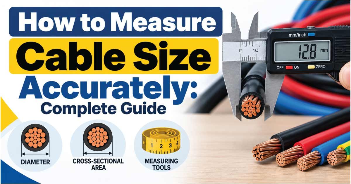
Knowing how to measure cable size is important when replacing electrical wiring, checking an existing installation, selecting a cable for a project, or verifying whether a conductor is suitable for a particular load. Cable size can refer to the conductor cross-sectional area, wire gauge, conductor diameter, or overall cable dimensions, depending on the measurement system being used.
The most reliable way to identify a cable size is to check its printed markings first. If the markings are missing or unreadable, you can measure the conductor diameter with a caliper and calculate its approximate cross-sectional area. For stranded cable, the calculation is slightly different because the conductor consists of multiple individual wires.
This guide explains how to measure cable size accurately, how to convert diameter into cross-sectional area, how AWG relates to metric cable sizes, and how to avoid common measurement mistakes.
What Does Cable Size Mean?
Cable size generally describes the size of the conductive material inside a cable. In metric systems, conductor size is commonly specified in square millimeters (mm²). In North America, wire size is often identified using American Wire Gauge (AWG).
The conductor size affects how much electrical current a cable can safely carry. However, cable selection is not determined by conductor size alone. Installation method, insulation temperature rating, ambient temperature, voltage drop, number of loaded conductors, and applicable electrical codes can also affect the allowable current.
A cable may therefore have several dimensions worth identifying:
- Conductor cross-sectional area: Usually stated in mm².
- Conductor diameter: The diameter of a solid conductor or individual strand.
- AWG size: A numerical wire-gauge designation.
- Number of cores: The number of insulated conductors within the cable.
- Overall cable diameter: The outside diameter including insulation and sheath.
- Stranding: The number and arrangement of individual conductor strands.
For electrical sizing, the conductor cross-sectional area or applicable wire gauge is generally more useful than the overall outside diameter.
How to Identify Cable Size From Its Markings
Before physically measuring a cable, inspect its insulation. Manufacturers commonly print information along the outside of electrical wire and cable.
Depending on the cable type, markings may identify:
- Conductor size in mm²
- AWG size
- Number of conductors
- Voltage rating
- Insulation type
- Temperature rating
- Manufacturer information
- Applicable cable designation
For example, a marking such as 2.5 mm² indicates a nominal conductor cross-sectional area of 2.5 square millimeters. A marking such as 12 AWG identifies the conductor using the American Wire Gauge system.
This is normally preferable to measuring the outside of the finished cable because insulation thickness varies between cable types.
Why Cable Markings Are Important
A measurement taken from the outside of a cable cannot reliably tell you the conductor size. Two cables can have similar outside diameters while having different conductor sizes because their insulation, shielding, fillers, and outer jackets differ.
If the manufacturer’s marking is clear and applicable to the cable, use it as the starting point rather than guessing from appearance.
How to Measure Cable Size With a Caliper
If cable markings are unavailable, a digital or vernier caliper can help determine the conductor diameter.
This method works particularly well for a solid conductor. For stranded conductors, additional calculation is required.
Step 1: Disconnect and Isolate the Cable
Never measure an exposed conductor while it is energized.
Before removing insulation or exposing the conductor:
- Turn off the appropriate circuit.
- Isolate the supply.
- Follow the applicable electrical safety procedure.
- Verify that the conductor is de-energized using an appropriate tester.
- Avoid relying solely on the position of a switch.
If you are unfamiliar with electrical isolation procedures, have the cable inspected by a qualified electrician.
Step 2: Expose a Short Section of Conductor
Carefully remove enough insulation to measure the conductor without damaging it.
For a solid copper conductor, the exposed metal will form one continuous piece. For stranded cable, you will see multiple small wires twisted together.
Avoid nicking or cutting the conductor because damage can change the effective cross-sectional area and compromise the cable.
Step 3: Measure the Conductor Diameter
Place the caliper jaws gently around the conductor.
Do not compress a stranded conductor excessively. Record the diameter in millimeters (mm) if possible.
For a solid conductor, take several measurements at different points. If the readings are consistent, use the measured diameter for the calculation.
Step 4: Calculate the Cross-Sectional Area
For a round solid conductor, use:
A = πd² / 4
Where:
- A = conductor cross-sectional area in mm²
- d = conductor diameter in mm
- π ≈ 3.14159
For example, if a solid conductor measures approximately 1.78 mm in diameter:
A = 3.14159 × (1.78²) / 4
This gives approximately 2.49 mm², which is close to a nominal 2.5 mm² conductor.
The measured result should be treated as an identification aid rather than proof of a cable’s current-carrying capacity.
Cable Diameter to Cross-Sectional Area Chart
For round solid conductors, the following values illustrate the mathematical relationship between conductor diameter and cross-sectional area.
| Nominal Area (mm²) | Approx. Diameter (mm) | Typical Identification |
|---|---|---|
| 0.5 | 0.80 | Small conductor |
| 0.75 | 0.98 | Small conductor |
| 1.0 | 1.13 | Small power/control conductor |
| 1.5 | 1.38 | Common general-purpose size |
| 2.5 | 1.78 | Common power-wiring size |
| 4 | 2.26 | Larger conductor |
| 6 | 2.76 | Larger power conductor |
| 10 | 3.57 | Heavy-duty conductor |
| 16 | 4.51 | Large conductor |
| 25 | 5.64 | Large power conductor |
| 35 | 6.68 | Large power conductor |
| 50 | 7.98 | Large conductor |
| 70 | 9.44 | High-capacity conductor |
| 95 | 11.00 | High-capacity conductor |
| 120 | 12.36 | High-capacity conductor |
These diameters are theoretical values for round conductors calculated from the stated cross-sectional area. Actual stranded conductors can have different measured dimensions because of strand arrangement and manufacturing construction.
How to Measure Stranded Cable Size
Measuring a stranded cable is more complicated than measuring a solid conductor.
A stranded conductor contains many individual wires, so measuring the outside diameter of the entire bundle and treating it as a solid circle can produce an inaccurate result. The spaces between strands mean that the bundle’s external diameter does not directly represent the amount of metal.
There are two useful approaches.
Method 1: Check the Cable Marking
The preferred method is to identify the manufacturer’s printed size.
For example, if a cable is marked 6 mm², the conductor is nominally specified by its cross-sectional area rather than by the outside diameter of the complete stranded bundle.
Method 2: Count and Measure the Strands
If the marking is unavailable, you can estimate the conductor area by examining the individual strands.
Measure the diameter of one strand and count the number of strands.
Use:
Total Area = Number of Strands × πd² / 4
For example, suppose a conductor contains 7 strands, each approximately 0.67 mm in diameter.
The area of one strand is:
A = π × 0.67² / 4
Multiply that result by seven to estimate the total metallic cross-sectional area.
This approach is useful for identification, but manufacturing tolerances and strand construction should be considered.
Do Not Measure the Complete Insulated Cable
The outside diameter of a stranded cable includes insulation and possibly a protective sheath. It cannot be directly converted into conductor area without knowing the cable’s construction.
How to Measure Cable Size Using AWG
American Wire Gauge (AWG) is a standardized wire-size system commonly used for electrical conductors in the United States and some other markets.
Unlike metric cable sizing, AWG numbers work in the opposite direction:
A smaller AWG number means a larger conductor.
For example, 10 AWG is larger than 14 AWG, while 18 AWG is smaller than 16 AWG.
A simplified comparison is shown below.
| AWG Size | Approx. Conductor Diameter (mm) | Approx. Area (mm²) |
|---|---|---|
| 18 AWG | 1.02 | 0.82 |
| 16 AWG | 1.29 | 1.31 |
| 14 AWG | 1.63 | 2.08 |
| 12 AWG | 2.05 | 3.31 |
| 10 AWG | 2.59 | 5.26 |
| 8 AWG | 3.26 | 8.37 |
| 6 AWG | 4.12 | 13.30 |
| 4 AWG | 5.19 | 21.15 |
| 2 AWG | 6.54 | 33.62 |
| 1 AWG | 7.35 | 42.41 |
| 1/0 AWG | 8.25 | 53.49 |
| 2/0 AWG | 9.27 | 67.43 |
| 3/0 AWG | 10.40 | 85.01 |
| 4/0 AWG | 11.68 | 107.20 |
These are approximate nominal conductor dimensions for AWG sizes. AWG and metric sizes are not exact one-to-one equivalents. When selecting cable, use the actual applicable standard and manufacturer’s specifications rather than automatically substituting one size for another.
Metric Cable Size vs AWG
Metric cable sizing and AWG describe conductor dimensions differently.
Metric sizes are normally expressed as cross-sectional area in mm², while AWG uses a gauge number based on a standardized geometric progression.
Some commonly encountered approximate comparisons are:
| Metric Size | Approx. AWG Equivalent | Note |
|---|---|---|
| 0.75 mm² | 18 AWG | Approximate |
| 1.0 mm² | 17 AWG | No exact common AWG match |
| 1.5 mm² | 15–16 AWG | Approximate |
| 2.5 mm² | 13–14 AWG | Approximate |
| 4 mm² | 11–12 AWG | Approximate |
| 6 mm² | 9–10 AWG | Approximate |
| 10 mm² | 7–8 AWG | Approximate |
| 16 mm² | 5–6 AWG | Approximate |
| 25 mm² | 3–4 AWG | Approximate |
| 35 mm² | 2–3 AWG | Approximate |
| 50 mm² | 1–1/0 AWG | Approximate |
Because these values are comparisons rather than exact substitutions, cable selection should always follow the requirements of the applicable electrical standard.
How to Measure Cable Size Without Removing the Insulation
Sometimes you cannot expose the conductor because the cable is installed, terminated, or otherwise difficult to access.
In this situation, the safest approach is to identify the cable through its:
- Printed jacket or insulation markings
- Manufacturer part number
- Installation documentation
- Electrical drawings
- Existing equipment specifications
- Cable datasheet
Measuring the overall cable diameter with a caliper can provide useful information for physical installation purposes, such as determining whether a cable will fit through a gland or conduit. However, it should not normally be used to determine conductor cross-sectional area.
Cable manufacturers can use different insulation thicknesses and constructions, so overall diameter is not a universal indicator of electrical conductor size.
Cable Size vs Current-Carrying Capacity
One of the most important misunderstandings about cable measurement is assuming that identifying the conductor size automatically tells you how much current it can safely carry.
It does not.
The allowable current, often called ampacity or current-carrying capacity, depends on several factors.
Important considerations include:
- Conductor material, such as copper or aluminum
- Conductor cross-sectional area
- Insulation temperature rating
- Ambient temperature
- Installation method
- Number of loaded conductors
- Cable grouping
- Enclosure or conduit conditions
- Voltage-drop requirements
- Local electrical regulations
- Continuous or intermittent loading
For this reason, a cable should not be selected solely because its diameter appears large enough.
Cable size identification and cable sizing are related but different tasks.
Identification tells you what cable you have. Sizing determines whether that cable is appropriate for the intended electrical load and installation conditions.
How to Choose the Correct Cable Size
After determining the existing cable size, the next question is often whether it is suitable for a new application.
Start by determining the electrical requirements.
1. Determine the Load
Identify the equipment’s rated power, current, and voltage.
For a simple resistive single-phase load, power and current can be related using:
P = V × I
Therefore:
I = P / V
For motors and other equipment, the calculation may require additional factors such as power factor and efficiency.
2. Consider Cable Length
Long cable runs can experience significant voltage drop. A conductor may have adequate current capacity but still require a larger size to keep voltage drop within the permitted limit.
3. Check Installation Conditions
The same conductor size can have different allowable current ratings depending on how it is installed.
Consider whether the cable is:
- In conduit
- In trunking
- Buried
- Installed in free air
- Bundled with other cables
- Exposed to high temperatures
4. Check the Applicable Standard
Electrical requirements vary by country, installation type, and application. Use the relevant electrical code, standard, engineering specification, or manufacturer’s data when making the final selection.
Common Mistakes When Measuring Cable Size
Even a simple cable measurement can produce misleading results if the wrong part of the cable is measured.
Measuring the Outer Jacket
The outer diameter includes insulation and protective materials. It is not the same as conductor size.
Treating Stranded Cable as Solid
The empty spaces between individual strands mean that the bundle’s outside diameter cannot simply be treated as the diameter of a solid conductor.
Using a Ruler for Small Conductors
Small differences in conductor diameter can represent substantial differences in cross-sectional area because area changes with the square of diameter.
A caliper provides much better measurement precision.
Ignoring Conductor Material
Copper and aluminum conductors of the same physical size do not necessarily have the same electrical performance for a given application.
Confusing Cable Size With Ampacity
A cable’s cross-sectional area is only one factor in determining its permissible current.
Assuming AWG and mm² Are Exact Equivalents
They are different sizing systems. A conversion chart should be treated as an approximate comparison unless the applicable standard specifies an acceptable equivalent.
Tools You Can Use to Measure Cable Size
You do not need a large collection of equipment for basic cable identification.
Useful tools include:
- Digital caliper: Best for measuring conductor diameter.
- Wire stripper: Used to carefully expose a conductor when appropriate.
- AWG wire gauge: Useful for identifying compatible wire gauges.
- Magnifying glass: Helpful when insulation markings are small or worn.
- Multimeter or voltage tester: Used as part of an appropriate electrical safety procedure to verify de-energization.
- Manufacturer datasheet: Useful for confirming cable construction and dimensions.
A caliper is generally more versatile than a simple ruler because it can measure small conductor diameters more precisely.
How to Measure Cable Size: Quick Procedure
For a quick reference, follow this sequence:
- Look for the cable marking before measuring anything.
- Identify whether the cable uses mm², AWG, or another designation.
- Make sure the cable is properly isolated and de-energized before exposing a conductor.
- Remove insulation carefully if physical measurement is necessary.
- Use a caliper to measure the conductor diameter.
- For a solid round conductor, calculate area using A = πd²/4.
- For stranded conductors, identify the strand count and diameter when appropriate.
- Compare the result with a recognized cable-size reference.
- Do not use conductor diameter alone to determine ampacity.
- Check voltage drop, installation conditions, applicable codes, and manufacturer information before selecting a cable for an electrical installation.
Frequently Asked Questions About Measuring Cable Size
How do I measure cable size in mm²?
Measure the conductor diameter with a caliper and calculate its cross-sectional area using A = πd²/4 if it is a solid round conductor. For stranded cable, determine the individual strand size and number of strands or use the manufacturer’s marking. The result should be confirmed against the cable specification.
Can I measure cable size from the outside diameter?
Usually, no. The outside diameter includes insulation, shielding, fillers, and the outer jacket, so it does not directly indicate conductor area. Overall diameter is useful for installation and cable-gland considerations, but conductor markings or direct conductor measurements are better for identifying electrical cable size.
How do I measure stranded wire size?
First check the manufacturer’s cable marking. If it is unavailable, count the strands and measure the diameter of an individual strand. Calculate the area of one strand and multiply it by the number of strands. Because construction can vary, confirm the result against manufacturer or standard information.
Is 2.5 mm² the same as 12 AWG?
No. They are not exact equivalents. A 2.5 mm² conductor has an area between common AWG sizes, while 12 AWG is approximately 3.31 mm². A conversion chart can provide an approximate comparison, but the applicable electrical standard should be used when selecting a replacement.
Does a larger cable always carry more current?
A larger conductor generally has greater current-carrying potential, but size alone does not determine allowable current. Insulation rating, installation method, ambient temperature, cable grouping, conductor material, voltage drop, and electrical regulations can all affect the final permissible current rating.
Conclusion
Learning how to measure cable size is useful for identifying existing wiring and understanding the dimensions of electrical conductors. The best starting point is always the manufacturer’s cable marking. When markings are unavailable, a caliper can be used to measure conductor diameter, followed by a cross-sectional-area calculation for a solid conductor.
For stranded cable, the individual strand construction must be considered rather than measuring the entire bundle as if it were solid.
Remember that cable size is not the same thing as ampacity. Before installing or replacing electrical cable, consider current demand, voltage drop, conductor material, insulation rating, installation conditions, and the requirements of the applicable electrical standard.
Accurate measurement helps identify a cable, but proper cable selection requires a complete electrical assessment.