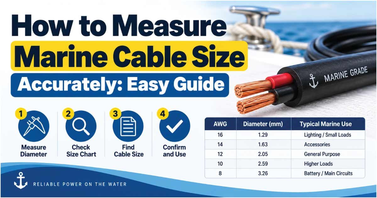
Choosing the correct marine cable size is more than checking the thickness of a wire. A boat’s electrical system must handle current safely while minimizing voltage loss over the cable run. Because marine wiring operates in a demanding environment with moisture, vibration, heat, and limited installation space, accurate cable sizing matters.
To measure marine cable size, you need to identify the conductor size, measure the cable length, determine the circuit current, establish the system voltage, and account for voltage drop and installation conditions. You also need to use cable intended for marine applications rather than assuming an ordinary automotive or household wire is suitable.
This guide explains how to measure marine cable size step by step, how AWG and metric sizes relate to conductor dimensions, how to calculate voltage drop, and how to select the appropriate cable for common boat circuits.
What Does Marine Cable Size Mean?
Marine cable size generally refers to the cross-sectional area of the electrical conductor and its ability to carry current. In North American boat wiring, conductor sizes are commonly identified using AWG (American Wire Gauge). Metric systems use square millimeters (mm²).
Cable size affects several important electrical characteristics:
- Current-carrying capacity
- Voltage drop
- Electrical resistance
- Heat generation
- Maximum practical circuit length
- Terminal and connector compatibility
A larger conductor has lower electrical resistance, which normally means less voltage loss and less heating for a given current and cable length.
It is important to distinguish conductor size from overall cable diameter. The outside diameter includes insulation, jacket, fillers, shielding, or multiple conductors. Measuring the outside of a cable does not automatically tell you the conductor’s electrical size.
Marine electrical systems also have specialized requirements. For example, the American Boat & Yacht Council (ABYC) publishes standards covering AC and DC electrical systems on boats, including wiring and connections.
Why Correct Marine Cable Sizing Matters
An undersized cable can create excessive resistance and voltage drop. Depending on the circuit and installation, this can cause equipment to operate poorly, cables to heat excessively, or protective devices and connections to become unsuitable for the intended load.
Oversizing is generally less problematic electrically, but an unnecessarily large cable can increase cost, weight, installation difficulty, and terminal requirements.
Correct sizing helps you achieve:
- Reliable equipment operation
- Acceptable voltage at the load
- Appropriate current-carrying capacity
- Better protection against excessive heating
- Easier installation and termination
- Compatibility with terminals, breakers, fuses, and connectors
Marine installations deserve particular attention because electrical conductors may be exposed to salt air, condensation, vibration, temperature changes, and mechanical movement.
The cable should therefore be selected based on the complete application rather than conductor diameter alone.
Tools Needed to Measure Marine Cable Size
You do not need sophisticated equipment to identify many marine cables. The tools required depend on whether you are measuring an existing cable or designing a new circuit.
Useful tools include:
- Digital caliper for measuring conductor diameter
- Wire stripper for safely exposing a conductor when permitted
- AWG wire gauge for identifying conductor size
- Tape measure for determining cable length
- Multimeter for checking electrical conditions
- Manufacturer’s cable specifications
- Current-rating and voltage-drop tables
- Appropriate documentation for the boat’s electrical system
If the cable is already installed, avoid removing insulation or disconnecting conductors unless you are qualified to do so and the circuit has been safely isolated.
A cable’s printing or marking is often the easiest starting point. Many marine cables have identification printed on the insulation or jacket showing conductor count, conductor size, voltage rating, temperature rating, or other information.
How to Measure Marine Cable Size Step by Step
The most reliable approach is to combine physical measurement with electrical requirements.
Step 1: Read the Cable Marking
Before cutting, stripping, or measuring anything, inspect the cable jacket.
Look for markings that may identify:
- AWG size
- mm² conductor area
- Number of conductors
- Voltage rating
- Temperature rating
- Manufacturer
- Marine or applicable certification markings
- Cable construction
For example, a cable marked with a conductor designation can often be identified without physically measuring the copper.
This is preferable because measuring the outside diameter can be misleading when the cable has thick insulation.
Step 2: Determine Whether It Is a Single or Multiconductor Cable
A marine cable may contain one conductor, two conductors, or several individually insulated conductors inside a common jacket.
For example, a two-conductor DC cable may contain:
- Positive conductor
- Negative conductor
Do not treat the outside diameter of a two-conductor cable as the conductor diameter. Each conductor must be evaluated separately.
Step 3: Expose the Conductor Only When Safe
If the cable marking is unavailable and the cable can be safely disconnected, expose a small section of conductor.
Copper should be measured rather than the insulation.
For stranded wire, the individual strands should remain intact. Do not use the diameter of one strand as the cable size.
Step 4: Measure the Conductor Diameter
Use a digital caliper to measure the diameter across the conductor.
For a circular conductor, the cross-sectional area can be estimated from its diameter:
A = π × d² ÷ 4
Where:
- A = conductor cross-sectional area
- d = conductor diameter
- π ≈ 3.1416
For example, if a solid conductor measures 2 mm across:
A = 3.1416 × 2² ÷ 4
A ≈ 3.14 mm²
However, stranded conductors are not always accurately identified by simply measuring the outside diameter of the entire bundle. Strand arrangement, compression, plating, and measurement technique can affect the result.
For that reason, a wire gauge, manufacturer’s specification, or verified conductor construction is usually preferable.
AWG Marine Cable Size vs. Metric Size
Marine electrical cables may be specified in either AWG or mm². These systems should not be treated as perfectly interchangeable because common sizes do not always correspond exactly.
The following table provides approximate conductor-area relationships rather than a substitute for a manufacturer’s specification.
| AWG | Approx. Area (mm²) | Typical Relative Size |
|---|---|---|
| 18 | 0.82 | Small |
| 16 | 1.31 | Small |
| 14 | 2.08 | Small–medium |
| 12 | 3.31 | Medium |
| 10 | 5.26 | Medium |
| 8 | 8.37 | Medium–large |
| 6 | 13.3 | Large |
| 4 | 21.1 | Large |
| 2 | 33.6 | Very large |
| 1/0 | 53.5 | Very large |
| 2/0 | 67.4 | Extra large |
| 4/0 | 107 | Extra large |
These values describe conductor cross-sectional area. They do not tell you the allowable current for every marine installation.
Current capacity depends on the cable construction, insulation temperature rating, ambient conditions, installation method, bundling, and the applicable standard or manufacturer’s instructions.
Measure Cable Length Correctly
Cable length is one of the most commonly overlooked factors in marine cable sizing.
For a typical DC circuit, electricity travels from the source to the load and returns to the source. Therefore, voltage-drop calculations normally consider the complete circuit path, not simply the physical distance between the battery and the equipment.
For example, if a bilge pump is 10 feet from the battery and the positive and negative conductors each travel approximately 10 feet, the circuit length used for voltage-drop calculation is approximately:
10 ft + 10 ft = 20 ft
The same principle applies to metric measurements.
| One-Way Distance | Approx. Round-Trip Length |
|---|---|
| 3 m | 6 m |
| 5 m | 10 m |
| 10 m | 20 m |
| 15 m | 30 m |
| 20 m | 40 m |
Measure the actual cable route, rather than simply measuring a straight line between two components. Allow for bends, service loops, connection points, and routing around equipment.
A longer cable run generally creates greater resistance and therefore greater voltage drop.
Determine the Current Requirement
The next step is to identify how much current the circuit will carry.
Look at the equipment nameplate, manufacturer’s documentation, or installation instructions.
Common marine electrical loads include:
- Bilge pumps
- Navigation lights
- Cabin lighting
- Radios
- Fish finders
- GPS equipment
- Refrigeration
- Water pumps
- Fans
- Inverters
- Electric motors
- Battery chargers
- Winches
Do not assume the current simply from the equipment’s physical size.
For a DC load, a basic relationship is:
Power = Voltage × Current
Therefore:
Current = Power ÷ Voltage
For example, a 120-watt load operating at 12 volts would theoretically draw:
120 W ÷ 12 V = 10 A
Actual equipment requirements can differ because of efficiency, operating conditions, startup current, and manufacturer specifications. Motors and compressors can also have significantly different starting and running characteristics.
Use the manufacturer’s stated current where available.
Understand Voltage Drop When Measuring Cable Size
Voltage drop is one of the most important reasons a marine circuit may require a larger cable than expected.
Every conductor has resistance. When current flows through that resistance, some voltage is lost before electricity reaches the load.
The basic relationship is:
V = I × R
Where:
- V = voltage drop
- I = current
- R = circuit resistance
As cable length increases, resistance increases. As conductor size increases, resistance decreases.
This creates a practical relationship:
Higher current + longer cable run = greater need for a larger conductor
This is especially important on lower-voltage systems. A small voltage loss represents a larger percentage of the available voltage in a 12-volt circuit than in a higher-voltage circuit.
For example, losing 1 volt from a 12-volt circuit represents a much larger percentage loss than losing 1 volt from a 120-volt circuit.
The acceptable voltage drop depends on the circuit, equipment, governing requirements, and manufacturer’s recommendations. Do not automatically apply one percentage to every marine circuit.
Use Resistance to Estimate Voltage Drop
If the conductor resistance is known, voltage drop can be calculated directly.
A simplified formula is:
Voltage Drop = Current × Resistance
If resistance is specified per unit length, multiply it by the complete circuit length first.
For example, suppose a conductor has a resistance of 0.005 ohms per meter, the circuit length is 20 meters, and the current is 10 amps.
Total resistance:
0.005 × 20 = 0.10 ohms
Voltage drop:
10 × 0.10 = 1.0 volt
This is a simplified example. Actual marine cable selection should use the correct resistance data for the conductor and the applicable installation requirements.
For stranded copper marine cable, use the manufacturer’s published resistance data whenever available.
Choose Marine Cable Based on More Than Gauge
Once you know the current, circuit length, voltage, and voltage-drop requirements, you can select a conductor size.
But conductor size is only one part of cable selection.
Consider these characteristics:
| Factor | Why It Matters |
|---|---|
| Conductor size | Determines resistance and current capability |
| Cable length | Affects total circuit resistance |
| Operating current | Determines electrical loading |
| System voltage | Determines the significance of voltage drop |
| Insulation rating | Must suit the environment and temperature |
| Flexibility | Important for moving or vibrating installations |
| Moisture resistance | Important in marine environments |
| Corrosion resistance | Important around saltwater and condensation |
| Number of conductors | Affects installation and overall cable diameter |
| Terminal compatibility | Ensures proper connections |
| Applicable standard | Establishes installation and safety requirements |
Marine cable should be specifically suitable for the intended marine application. A cable that looks physically similar to marine cable is not automatically equivalent.
Marine Cable Size Selection Example
Consider a hypothetical 12-volt DC pump.
Suppose:
- System voltage = 12 V
- Equipment current = 8 A
- One-way cable route = 15 ft
- Round-trip circuit length = 30 ft
- Copper conductor
- Flexible marine installation
The first step is not to immediately choose an AWG number.
Instead, establish:
- The equipment’s actual operating current.
- The complete positive and negative cable length.
- The required voltage-drop limit for the circuit.
- The cable’s allowable current under the applicable installation conditions.
- The manufacturer’s cable specifications.
- The appropriate fuse or circuit protection.
Then compare candidate conductor sizes using the applicable marine sizing table or calculator.
If a smaller cable meets the current requirement but produces excessive voltage drop, increase the conductor size.
This illustrates an important point: marine cable sizing is not simply an ampacity calculation.
How to Measure an Existing Marine Cable Without Guessing
If you are replacing an existing cable, start by identifying everything printed on the cable.
Then follow this sequence:
Check the Marking
Look for the conductor gauge or metric area.
Check the Conductor Count
Determine whether the cable contains one, two, or multiple conductors.
Verify the Application
Identify what the cable powers and its approximate current.
Measure the Route
Determine the actual positive and negative circuit length.
Verify Voltage
Confirm whether the system is 12 V, 24 V, 48 V, AC, or another configuration.
Check Voltage Drop
Make sure the existing or replacement cable provides suitable performance for the load.
Confirm Protection
The fuse or breaker must be appropriate for the circuit and cable installation.
If the existing cable is damaged, corroded, unusually warm, or improperly protected, do not assume that replacing it with the same size automatically solves the problem. The original installation may itself have been incorrectly designed.
Common Marine Cable Sizing Mistakes
Several mistakes occur repeatedly when measuring and selecting boat cable.
Measuring Insulation Instead of Copper
The outside diameter of the cable does not directly identify conductor size.
Ignoring the Return Path
Using only the one-way distance can underestimate voltage-drop-related resistance in a DC circuit.
Choosing Cable Only by Amperage
A cable may have sufficient current capacity but still create excessive voltage drop over a long run.
Using Automotive Wire Without Checking Suitability
Marine environments require appropriate cable construction and installation practices.
Ignoring Starting Current
Motors, pumps, compressors, and other inductive loads may behave differently during startup.
Using an Approximate Gauge Conversion
AWG and mm² sizes are related but not identical. Use actual manufacturer specifications when precision matters.
Ignoring Installation Conditions
Temperature, bundling, routing, and enclosure conditions can influence allowable conductor loading.
Replacing Cable Without Checking Protection
Cable size, circuit protection, and equipment requirements must be considered together.
Marine Cable vs. Automotive Cable
Marine and automotive electrical systems may both use low-voltage DC power, but the installation environment can be very different.
Marine wiring can encounter:
- Saltwater exposure
- High humidity
- Condensation
- Continuous vibration
- Restricted ventilation
- Mechanical movement
- Corrosive environments
Marine-grade cable is designed for the relevant application and should be selected according to the applicable specifications.
Another important consideration is conductor construction. Flexible stranded copper conductors are commonly used where vibration and movement are expected. The exact construction, insulation, temperature rating, and certification should still be verified from the cable manufacturer.
When Should You Use a Larger Marine Cable?
Increasing conductor size can be appropriate when:
- The cable run is long.
- The load current is high.
- The system voltage is low.
- The calculated voltage drop is too high.
- The installation conditions reduce allowable ampacity.
- The equipment manufacturer specifies a larger conductor.
- The cable will experience significant operating temperature.
- Future expansion has been deliberately included in the design.
However, simply installing the largest available cable is not always the best solution.
Large cables cost more, occupy more space, may require larger terminals, and can be harder to route. The goal is to select a cable that satisfies the electrical, environmental, mechanical, and installation requirements of the circuit.
Quick Marine Cable Measurement Checklist
Before purchasing or installing a replacement cable, record the following:
- System voltage
- Equipment current
- One-way cable length
- Round-trip circuit length
- Conductor material
- AWG or mm² size
- Number of conductors
- Cable insulation type
- Operating temperature
- Installation environment
- Required voltage drop
- Applicable marine standard
- Fuse or breaker rating
- Manufacturer’s cable recommendations
Keeping these details together makes cable selection much easier and reduces the risk of choosing a cable based only on appearance.
Frequently Asked Questions About Measuring Marine Cable Size
How do I measure marine cable size?
First check the cable marking for AWG or mm² information. If the marking is unavailable, safely expose the conductor and measure the conductor rather than the insulation. A wire gauge or manufacturer’s specification is usually more reliable than measuring the outside diameter of a stranded conductor.
Is marine cable size measured by diameter or gauge?
Marine cable can be identified by AWG gauge or metric conductor area in mm². Diameter can help identify an unknown conductor, but outside cable diameter includes insulation and other materials. Therefore, overall cable diameter should not be used as the sole method of determining electrical conductor size.
How does cable length affect marine wire size?
Longer cable runs create more electrical resistance and therefore greater voltage drop. In a typical DC circuit, both the outgoing and return conductors contribute to the circuit length. A longer run may require a larger conductor even when the equipment’s current requirement has not changed.
What size cable should I use for a 12V marine system?
There is no single cable size that is correct for every 12V marine circuit. The required size depends on current, complete circuit length, allowable voltage drop, cable construction, installation conditions, and applicable requirements. Use the equipment manufacturer’s specifications and an appropriate marine cable-sizing table or calculator.
Can I use automotive wire on a boat?
You should not assume that automotive wire is suitable simply because both systems use DC electricity. Marine installations can involve moisture, salt exposure, vibration, and other demanding conditions. Select cable specifically suitable for the marine application and verify its construction, ratings, and applicable installation requirements.
Final Tips for Accurate Marine Cable Measurement
Measuring marine cable size correctly starts with identifying the actual conductor size, but proper cable selection goes further.
Remember these key points:
- Read the cable markings before measuring anything.
- Measure the conductor rather than the insulation.
- Use AWG or mm² specifications whenever available.
- Measure the complete cable route.
- Account for the return conductor in DC voltage-drop calculations.
- Determine the actual equipment current.
- Consider starting current for motors and similar loads.
- Check voltage drop as well as ampacity.
- Select cable suitable for marine conditions.
- Verify terminals and circuit protection.
- Follow the applicable marine electrical standard and manufacturer instructions.
For U.S. boat installations, ABYC E-11 covers AC and DC electrical systems on boats, making applicable standards an important part of professional marine electrical work.
If the circuit involves high current, battery banks, engine starting systems, shore power, inverters, or complex electrical distribution, professional electrical guidance is appropriate.
Conclusion
Learning how to measure marine cable size requires more than measuring the outside of a wire. You need to identify the conductor size, determine the actual circuit length, calculate the expected current, evaluate voltage drop, and select cable appropriate for the marine environment.
For an existing cable, begin with its markings and verify the conductor size. For a new installation, start with the electrical load and cable route before selecting the conductor. Always consider the complete circuit, including the return path, and use manufacturer specifications and applicable marine standards when determining the final cable size.
The right cable is one that safely handles the electrical load, provides acceptable voltage at the equipment, and is suitable for the conditions in which the boat operates.