
A cable tray provides a structured pathway for electrical power cables, control cables, instrumentation cables, communication cables, and other wiring systems. Selecting the correct tray size is important because the tray must provide enough space for the cables while maintaining suitable separation, support, ventilation, and accessibility.
A cable tray size chart helps electricians, engineers, contractors, and installers compare common tray widths, depths, lengths, and applications. However, tray selection should not be based on width alone. The number and diameter of cables, cable weight, installation environment, support spacing, future expansion, and applicable electrical requirements all influence the final selection.
This guide explains common cable tray sizes, cable capacity, width and depth selection, ladder and perforated trays, load considerations, installation factors, and practical cable tray sizing methods.
What Is a Cable Tray?
A cable tray is a mechanical support system used to route and support electrical cables in an organized manner.
Cable trays are commonly installed in:
- Industrial facilities
- Commercial buildings
- Power plants
- Manufacturing plants
- Data centers
- Warehouses
- Utility installations
- Solar power systems
- Control rooms
- Electrical substations
- Infrastructure projects
Unlike conduit, a cable tray generally provides an open or partially open pathway. This makes cable installation, inspection, maintenance, and future additions easier in many applications.
Cable trays are available in different widths, depths, materials, and configurations to accommodate different cable quantities and loads.
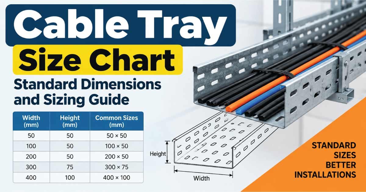
Cable Tray Size Chart
Cable tray dimensions are normally specified by width × depth × length.
The following chart shows common tray sizes used for general planning.
| Tray Width | Typical Depth | Common Application |
|---|---|---|
| 50 mm (2 in) | 25–50 mm | Small control and instrumentation cables |
| 75 mm (3 in) | 50–75 mm | Small cable groups |
| 100 mm (4 in) | 50–75 mm | Control and small power cables |
| 150 mm (6 in) | 50–100 mm | Small power installations |
| 225 mm (9 in) | 50–100 mm | Medium cable quantities |
| 300 mm (12 in) | 50–150 mm | Power and control cables |
| 450 mm (18 in) | 75–150 mm | Medium to large cable groups |
| 600 mm (24 in) | 75–150 mm | Large power distribution |
| 750 mm (30 in) | 100–150 mm | High cable quantities |
| 900 mm (36 in) | 100–150 mm | Large industrial installations |
| 1000 mm (40 in) | 100–150 mm | High-capacity cable routing |
| 1200 mm (48 in) | 100–150 mm | Major cable distribution systems |
Actual available sizes vary by manufacturer and cable tray system.
Understanding Cable Tray Dimensions
Three dimensions are particularly important when selecting a tray:
Width × Depth × Length
For example, a tray described as 600 × 100 mm generally has:
- 600 mm width
- 100 mm depth
The length is normally specified separately according to the tray section being supplied.
Tray Width
Width determines how much horizontal space is available for cables.
Larger numbers of cables or larger cable diameters generally require a wider tray.
Tray Depth
Depth determines the vertical space available for cables.
A deeper tray can accommodate a larger cable arrangement, but depth should not be selected simply to maximize cable quantity. Cable arrangement, heat dissipation, loading, and installation requirements also matter.
Tray Length
Cable tray sections are manufactured in standard lengths, although exact lengths vary by manufacturer.
Common section lengths may include:
- 2 m
- 2.4 m
- 3 m
- 6 m
The appropriate section length depends on the tray system and project requirements.
Cable Tray Width Selection
Tray width is one of the most important dimensions.
To determine the required width, first estimate the total horizontal space occupied by the cables.
For cables installed side by side:
Required Width ≈ Sum of Cable Outside Diameters + Allowance
For example, if several cables each have different outside diameters, add their actual diameters rather than using their conductor sizes.
A cable labeled 4-core 25 mm² does not have an outside diameter of 25 mm. The 25 mm² value refers to the conductor cross-sectional area.
The complete cable diameter includes:
- Conductor
- Insulation
- Filler
- Shielding where applicable
- Armor where applicable
- Outer sheath
Therefore, tray sizing should use the manufacturer’s actual cable outside diameter.
Cable Tray Fill Capacity
Cable tray fill is different from conduit fill.
A conduit completely surrounds the cables, while a tray provides an open support surface. The acceptable cable arrangement therefore depends on the tray type, cable type, installation method, heat dissipation, and applicable requirements.
For planning purposes, it is generally useful to avoid filling the tray to its absolute physical limit.
Allowing spare space can provide:
- Easier cable installation
- Better organization
- Improved maintenance access
- Space for future cables
- Reduced congestion
- Better heat dissipation
The exact allowable cable arrangement should be determined according to the relevant tray standard and project specifications.
Cable Tray Size Based on Cable Diameter
Cable diameter is a practical way to estimate tray width.
| Approx. Cable Diameter | Approx. Number of Cables | Tray Width to Evaluate |
|---|---|---|
| 10 mm | 10 | 150 mm |
| 15 mm | 10 | 225 mm |
| 20 mm | 10 | 225–300 mm |
| 25 mm | 10 | 300 mm |
| 30 mm | 10 | 300–450 mm |
| 40 mm | 10 | 450–600 mm |
| 50 mm | 10 | 600 mm |
| 60 mm | 10 | 600–750 mm |
| 75 mm | 10 | 900 mm |
| 100 mm | 10 | 1200 mm |
These are planning examples rather than universal cable tray capacities. The final tray size must account for actual cable dimensions, arrangement, spacing, weight, tray loading, and applicable requirements.
How to Calculate Cable Tray Width
A simple preliminary method is to calculate the total width occupied by the cables.
Example
Suppose a tray needs to carry:
- 6 power cables with an outside diameter of 30 mm
- 8 control cables with an outside diameter of 15 mm
The approximate occupied width is:
6 × 30 = 180 mm
8 × 15 = 120 mm
Total:
180 + 120 = 300 mm
A tray wider than 300 mm would then be evaluated, with additional allowance for spacing, installation, and future expansion.
The final selection should not be based solely on this arithmetic because cable arrangement and thermal considerations may require additional space.
Discover More:
Cable Tray Depth Selection
Cable tray depth affects both cable capacity and physical arrangement.
Common depths include:
- 25 mm
- 50 mm
- 75 mm
- 100 mm
- 150 mm
- 200 mm
- 300 mm
Shallow trays can be suitable for small control or instrumentation cables.
Deeper trays may be appropriate for larger cable groups or installations where vertical cable arrangement requires additional space.
However, deeper does not always mean better. The tray should be selected according to the actual cable quantity, cable weight, support system, and installation requirements.
Cable Tray Types
Several cable tray designs are available.
Ladder Cable Tray
A ladder cable tray has two longitudinal side rails connected by rungs.
It provides excellent ventilation and is commonly used for:
- Large power cables
- Industrial installations
- Heavy cable systems
- Long cable runs
The open structure can also make cable installation easier.
Perforated Cable Tray
A perforated tray has a continuous base containing ventilation holes.
It provides more support under smaller cables than a ladder tray.
Typical applications include:
- Control cables
- Instrumentation
- Power cables
- Commercial wiring
Solid Bottom Cable Tray
Solid-bottom trays provide a continuous supporting surface.
They can be useful where additional cable support or protection is desired.
Because ventilation is different from an open ladder tray, thermal considerations should be evaluated carefully.
Wire Mesh Cable Tray
Wire mesh tray is made from welded wire sections.
It is commonly used for:
- Data cables
- Communication cables
- Control wiring
- Smaller electrical cables
Its lightweight structure can make it convenient for indoor installations.
Discover More:
Cable Tray Material
Cable trays are manufactured from different materials.
Galvanized Steel
Galvanized steel provides strong mechanical performance and corrosion protection.
It is commonly used in:
- Industrial facilities
- Commercial buildings
- Electrical rooms
- Outdoor installations
Stainless Steel
Stainless steel provides excellent corrosion resistance and can be used in demanding environments.
It may be selected for:
- Food-processing facilities
- Chemical environments
- Coastal locations
- Corrosive industrial areas
Aluminum
Aluminum cable trays are lightweight and corrosion resistant.
They can be useful where:
- Low weight is important
- Corrosion resistance is required
- Installation access is limited
FRP Cable Tray
Fiber-reinforced plastic (FRP) trays can provide corrosion resistance and electrical insulation characteristics.
They may be used in chemical plants, wastewater facilities, and other aggressive environments.
Discover More:
Cable Tray Load Capacity
Cable weight is a major factor when selecting a tray.
A tray must safely support the combined weight of the cables between support points.
Cable tray load depends on:
- Cable weight
- Tray width
- Tray material
- Tray depth
- Support span
- Cable arrangement
- Installation environment
For example, a tray carrying many large armored power cables may experience significantly greater loading than a tray carrying lightweight control cables.
The tray manufacturer’s load-span data should be used for final structural selection.
Cable Tray Support Spacing
Cable trays require suitable mechanical support.
Support methods may include:
- Trapeze supports
- Wall brackets
- Ceiling supports
- Floor supports
- Unistrut-type framing
- Cantilever brackets
Support spacing depends on the tray construction and manufacturer.
A tray designed for a short support span may not safely carry the same load when supports are installed farther apart.
Therefore, both tray size and support span must be considered when designing a cable tray system.
Cable Tray for Power Cables
Power cables are generally larger and heavier than control or communication cables.
When sizing a tray for power cables, consider:
- Cable outside diameter
- Cable weight
- Number of cables
- Voltage level
- Cable arrangement
- Heat dissipation
- Separation requirements
- Short-circuit forces where applicable
- Future expansion
Large power cables may require ladder trays because of their weight and the need for effective ventilation.
Cable Tray for Control Cables
Control cables generally have smaller diameters and lower weight than large power cables.
Common applications include:
- Motor control
- Industrial automation
- Instrumentation
- PLC systems
- Control panels
- Process control
Perforated or wire mesh trays are frequently evaluated for these applications.
However, control and power cables may need separation to minimize electrical interference and satisfy installation requirements.
Cable Tray for Data and Communication Cables
Data and communication cables have different requirements from power cables.
Examples include:
- Ethernet cables
- Fiber-optic cables
- Coaxial cables
- Telephone cables
- Communication cables
Tray selection should consider:
- Cable bend radius
- Cable separation
- Electromagnetic interference
- Cable weight
- Future expansion
- Required cable organization
A tray that is physically large enough may still be unsuitable if cable separation or bend-radius requirements are not satisfied.
Cable Tray Size and Future Expansion
One of the most useful practices in cable tray design is allowing room for future cables.
A tray that is completely filled during the initial installation can make future expansion difficult.
Spare capacity can provide space for:
- Additional power cables
- New control cables
- Communication wiring
- Equipment upgrades
- Plant expansion
- Replacement cables
The amount of future capacity required depends on the project and owner requirements.
Cable Tray vs Conduit
Cable tray and conduit both provide pathways for electrical wiring, but they serve different installation needs.
| Feature | Cable Tray | Conduit |
|---|---|---|
| Cable access | Easy | More restricted |
| Multiple cables | Excellent | Limited by fill |
| Ventilation | Generally good | Limited |
| Future cable additions | Easier | More difficult |
| Large cable systems | Very suitable | Can be difficult |
| Visual organization | Good | Excellent when concealed |
| Maintenance | Convenient | More labor intensive |
| Long industrial runs | Often advantageous | Can require many fittings |
The appropriate choice depends on the building design, environmental conditions, cable type, mechanical protection requirements, and electrical regulations.
How to Choose the Correct Cable Tray Size
Follow these steps when selecting a cable tray.
1. List All Cables
Create a cable schedule showing:
- Cable type
- Number of cables
- Number of cores
- Conductor size
- Outside diameter
- Cable weight
- Voltage rating
2. Determine Cable Arrangement
Decide whether cables will be:
- Side by side
- Stacked
- Separated by type
- Installed in multiple layers
- Divided between different trays
3. Calculate Required Width
Add the cable outside diameters and provide appropriate installation allowance.
4. Select Tray Depth
Choose a suitable depth based on cable arrangement and the tray manufacturer’s specifications.
5. Check Cable Weight
Calculate the total weight per unit length and compare it with the tray’s load capacity.
6. Check Support Span
Make sure the selected tray can carry the expected load at the proposed support spacing.
7. Check Environment
Consider:
- Indoor or outdoor installation
- Moisture
- Corrosion
- UV exposure
- Chemicals
- Temperature
- Physical damage
8. Allow for Future Expansion
Provide reasonable spare capacity when required by the project.
Common Cable Tray Sizing Mistakes
Choosing Tray Width Only by Cable Count
Ten small cables and ten large power cables do not occupy the same amount of space.
Ignoring Cable Diameter
Cable outside diameter is more useful for physical tray sizing than conductor cross-sectional area alone.
Ignoring Cable Weight
A tray can have enough physical space but still be unsuitable for the cable load.
Using Excessive Support Spacing
Support span directly affects the structural capacity of the tray.
Mixing All Cable Types Without Separation
Power, control, instrumentation, and communication cables may require separation depending on the installation.
Leaving No Expansion Space
A completely filled tray can create maintenance and expansion problems later.
Selecting the Tray Without Checking the Environment
A standard steel tray may not be suitable for highly corrosive or chemically aggressive environments.
Cable Tray Size FAQs
What is the standard cable tray size?
There is no single standard cable tray size for every installation. Common widths include 100, 150, 300, 450, 600, 750, 900, and 1200 mm, while depth varies according to the tray system. The correct size depends on cable quantity, diameter, weight, and installation requirements.
How do I calculate cable tray size?
Start by identifying the outside diameter and number of cables. Add the cable widths for the proposed arrangement, provide suitable installation and future-expansion allowance, then select a tray width and depth that can safely support the total cable weight at the required support span.
What cable tray size is suitable for power cables?
Large power cables often require wider and deeper trays, particularly when the cables are heavy or numerous. Common sizes such as 300, 450, 600, 750, and 900 mm may be evaluated, but the final tray depends on actual cable diameter, weight, arrangement, and support conditions.
What is the difference between ladder and perforated cable tray?
A ladder tray has side rails and rungs, providing excellent ventilation and convenient access for large power cables. A perforated tray has a continuous base with openings and provides greater support for smaller cables. Selection depends on cable type, weight, ventilation, and installation requirements.
Can power and control cables be installed on the same tray?
They may be installed in the same overall cable-tray system in some applications, but appropriate separation may be required to reduce electromagnetic interference and meet installation requirements. Dividers or separate trays may be used when power and sensitive control or instrumentation cables need additional separation.
Conclusion
A cable tray size chart provides a useful starting point for selecting tray dimensions, but tray width and depth are only part of the design.
The correct cable tray should accommodate the number and outside diameter of cables, provide appropriate space for installation and future expansion, and safely support the total cable weight between support points.
Common tray widths range from small 50 mm and 100 mm trays to large 900 mm and 1200 mm systems, while depths commonly range from approximately 25 mm to 150 mm or more.
For reliable cable tray selection, always evaluate cable diameter, cable weight, tray material, tray type, support spacing, environmental conditions, cable separation, ventilation, and applicable installation requirements. This approach helps create a safer, more organized, accessible, and expandable electrical cable management system.