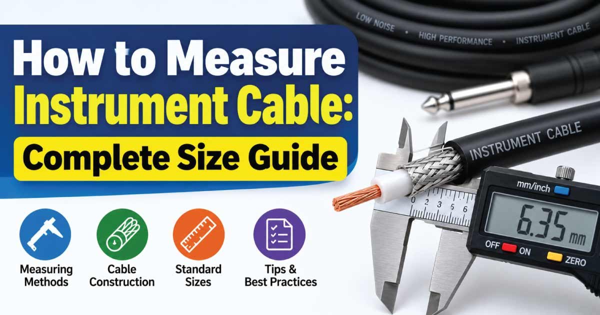
Measuring an instrument cable correctly is important when identifying an existing cable, selecting a replacement, checking installation requirements, or verifying whether a cable is suitable for a particular control or instrumentation system. Unlike ordinary electrical wire, instrument cable is designed to transmit low-level signals accurately while helping protect those signals from electrical interference.
The term “instrument cable size” can refer to several different measurements, including conductor size, outside diameter, number of pairs, shielding, and overall cable construction. Simply measuring the outside diameter is therefore not enough to identify an instrument cable completely.
This guide explains how to measure instrument cable step by step, including conductor diameter, cross-sectional area, cable outside diameter, pair configuration, shielding, and cable length. It also explains how to read cable markings, understand common sizes, avoid measurement mistakes, and select the correct replacement.
What Is Instrument Cable?
Instrument cable is a specialized cable used to transmit electrical signals between instruments, sensors, controllers, transmitters, monitoring equipment, and control systems.
It is commonly found in:
- Industrial automation systems
- Process control installations
- Temperature measurement systems
- Pressure and flow instrumentation
- Chemical and manufacturing plants
- Power generation facilities
- Building control systems
- Data acquisition equipment
Instrument cables may contain single conductors, twisted pairs, multiple pairs, shields, drain wires, and protective jackets, depending on their intended application.
Because instrumentation signals can be relatively small, cable construction is important. Shielding and proper cable selection can help reduce unwanted electromagnetic and radio-frequency interference.
Why Instrument Cable Size Matters
The conductor size affects electrical resistance and voltage drop, while the overall construction affects installation, signal integrity, mechanical protection, and compatibility with terminals or cable glands.
When identifying an instrument cable, it is useful to record more than just the conductor size.
Important characteristics can include:
- Conductor size
- Number of conductors or pairs
- Conductor material
- Insulation type
- Shielding arrangement
- Drain wire
- Overall diameter
- Jacket material
- Voltage and temperature ratings
- Manufacturer identification
What Measurements Should You Take?
Before measuring an instrument cable, determine what information you actually need.
For cable identification, the most useful measurements are usually:
| Measurement | What It Tells You | How It Is Measured |
|---|---|---|
| Conductor diameter | Approximate conductor size | Caliper or micrometer |
| Conductor area | Electrical cross-sectional area | Calculation or specification |
| Overall diameter | Physical cable size | Digital caliper |
| Cable length | Installation/current-path length | Tape measure or measured route |
| Number of conductors | Cable configuration | Visual inspection |
| Number of pairs | Instrumentation configuration | Visual inspection |
| Shield type | Interference protection arrangement | Visual inspection |
| Jacket thickness | Outer protection construction | Physical inspection |
Not every measurement is required for every job. If you are replacing an existing cable, identifying the cable marking and construction may be more useful than calculating the conductor area yourself.
Tools Needed to Measure Instrument Cable
A few basic tools can make cable measurement easier and more accurate.
Recommended tools include:
- Digital caliper
- Micrometer
- Measuring tape
- Ruler
- Wire gauge tool
- Cable stripping tool, where appropriate
- Calculator
- Camera or notes for recording markings
- Manufacturer datasheet for verification
A digital caliper is particularly useful because it can measure both small conductor dimensions and larger cable diameters.
Do not damage a cable simply to obtain a measurement. If the conductor is already accessible at an unused end, measurement is easier. For an installed or operational cable, rely on its identification markings and documentation whenever possible.
How to Measure Instrument Cable Step by Step
The following method works for identifying most conventional instrument cables.
1. Make the Cable Safe
Before inspecting or stripping a cable, ensure the relevant circuit is safely isolated.
Instrument cables can connect to control systems, sensors, transmitters, power supplies, or other equipment. Follow the appropriate isolation procedures before handling exposed conductors.
Never assume that a cable is safe simply because it carries an instrumentation signal.
2. Read the Cable Jacket Markings
Start by examining the outer jacket.
Manufacturers commonly print identification information along the cable. Depending on the cable type, markings may include:
- Conductor size
- Number of pairs
- Number of conductors
- Cable type
- Shield designation
- Voltage rating
- Temperature rating
- Manufacturer
- Applicable certification or standard
A marking such as 18 AWG 2 Pair Shielded provides substantially more information than outside diameter alone.
Record all visible markings before taking physical measurements.
3. Measure the Overall Cable Diameter
Use a digital caliper to measure the outside diameter of the complete cable.
Place the caliper gently around the cable and avoid compressing a soft jacket.
For best results:
- Clean the cable surface.
- Position the caliper perpendicular to the cable.
- Apply light pressure.
- Record the measurement.
- Repeat at another location if necessary.
The result is the overall cable diameter, not the conductor diameter.
This measurement is particularly useful when checking whether the cable will fit through a conduit, cable gland, connector, tray opening, or enclosure entry.
4. Count the Conductors
If the cable end is accessible, identify the number of individual conductors.
Instrument cable constructions may include:
- Single conductor
- Two conductors
- Three or more conductors
- Twisted pairs
- Multiple twisted pairs
- Triads
- Individually shielded pairs
- Overall shielded constructions
Counting the conductors helps identify the cable configuration.
5. Identify Twisted Pairs
Many instrumentation systems use twisted-pair cable because twisting can help reduce susceptibility to certain forms of electrical interference.
A cable described as 2-pair normally contains two pairs of conductors, giving four individual conductors, although the exact construction should always be verified.
Record both:
- Number of pairs
- Number of conductors
This distinction becomes important when ordering replacement cable.
6. Inspect the Shielding
Shielding is another important part of instrument cable identification.
Depending on construction, a cable may use:
- Overall foil shield
- Overall braided shield
- Individual pair shields
- Combined foil and braid
- Drain wire
- Multiple shielding layers
Do not assume that two cables with the same conductor size and number of pairs are equivalent. Their shielding construction may be different.
7. Measure the Conductor Diameter
If the conductor is accessible and measurement is appropriate, use a micrometer or digital caliper to measure the conductor.
For a solid round conductor, measure straight across the copper.
For a stranded conductor, the measurement is more complicated because the conductor consists of multiple individual strands.
The conductor’s actual electrical area is normally best obtained from the cable specification rather than estimating it from the outside diameter of the stranded bundle.
How to Calculate Instrument Cable Cross-Sectional Area
For a solid round conductor, the cross-sectional area can be calculated using:
A = π × d² ÷ 4
Where:
- A = conductor cross-sectional area
- d = conductor diameter
- π = approximately 3.1416
For example, if a solid conductor measures 1.02 mm in diameter:
A ≈ 3.1416 × 1.02² ÷ 4
A ≈ 0.82 mm²
This provides an approximate geometric cross-sectional area.
However, this calculation should not automatically be applied to the complete outside diameter of an insulated instrument cable. Insulation, shielding, fillers, separators, and the outer jacket all contribute to the overall diameter.
Instrument Cable AWG and Metric Sizes
Instrument cables are commonly specified using AWG or metric conductor area, depending on the manufacturer and market.
Some commonly encountered conductor sizes include:
| AWG | Nominal Conductor Area (mm²) | General Identification |
|---|---|---|
| 24 AWG | 0.205 mm² | Small signal conductors |
| 22 AWG | 0.326 mm² | Small instrumentation conductors |
| 20 AWG | 0.519 mm² | Instrument and control applications |
| 18 AWG | 0.823 mm² | Common control/instrumentation size |
| 16 AWG | 1.31 mm² | Larger conductors |
| 14 AWG | 2.08 mm² | Higher-current control applications |
| 12 AWG | 3.31 mm² | Larger electrical/control circuits |
These are nominal conductor areas associated with the AWG system. They should not be interpreted as a universal instrument-cable ampacity chart.
The correct conductor size depends on the particular circuit, equipment requirements, cable construction, installation conditions, and applicable specifications.
How to Measure Instrument Cable Outside Diameter
The outside diameter is often the easiest physical measurement to obtain.
Use a caliper rather than a ruler when greater precision is required.
Why Outside Diameter Is Important
Cable outside diameter can affect:
- Cable gland selection
- Conduit fill
- Tray capacity
- Connector compatibility
- Bend radius
- Installation space
- Pulling requirements
- Enclosure entry size
However, outside diameter does not directly identify conductor size.
Two cables can have the same conductor size but different overall diameters because one may contain additional shielding, fillers, armor, insulation, or protective layers.
How to Measure Instrument Cable Length
Cable length matters when designing or checking an instrumentation circuit.
Measure the actual cable route rather than simply measuring the straight-line distance between two pieces of equipment.
Consider:
- Equipment location
- Cable tray route
- Conduit route
- Vertical runs
- Service loops
- Termination allowance
- Routing around equipment
For an installed cable, the total physical route can be measured using the cable path.
For a new installation, calculate the route length and allow appropriate installation and termination allowance according to the project requirements.
Why Cable Length Matters
Longer conductors have greater resistance. In certain instrumentation circuits, this can influence signal transmission, voltage drop, loop performance, or sensor operation.
For this reason, cable length should be considered together with conductor size and the requirements of the connected equipment.
Instrument Cable Size vs Overall Cable Size
These two measurements are often confused.
Instrument cable conductor size refers to the electrical conductor itself.
Overall cable size generally refers to the complete outside diameter.
For example, a cable may contain relatively small conductors but have a much larger overall diameter because it contains:
- Multiple pairs
- Pair shields
- Overall shielding
- Drain wires
- Fillers
- Inner jackets
- Armor
- Outer protective jacket
Therefore, if someone asks for the “instrument cable size,” clarify whether they mean conductor size, number of pairs, or overall diameter.
How to Identify Instrument Cable From Its Markings
Cable markings are usually the fastest way to identify an existing cable.
Suppose the jacket indicates information similar to:
18 AWG – 2 Pair – Shielded
This tells you several important characteristics:
- Conductor gauge: 18 AWG
- Pair count: 2
- Shielding: present
However, it may not provide every required specification. You may still need to determine:
- Insulation material
- Jacket material
- Temperature rating
- Voltage rating
- Shield type
- Armor
- Manufacturer
- Certification
- Environmental rating
When replacing cable, match the complete specification rather than ordering based only on AWG.
How to Choose the Correct Instrument Cable Size
Measuring an existing cable is different from selecting a new one.
When choosing an instrument cable, consider the entire application.
Conductor Size
Select a conductor size compatible with the circuit’s electrical requirements and the equipment manufacturer’s specifications.
Number of Pairs
Determine how many signal circuits must be carried in the cable.
For example, a system requiring multiple independent signals may need a multi-pair cable rather than a single twisted pair.
Shielding
Shielding requirements depend on the signal and the surrounding electromagnetic environment.
Some applications require an overall shield, while others may require individually shielded pairs or a different construction.
Environmental Conditions
Check whether the cable will be exposed to:
- Heat
- Moisture
- Chemicals
- Oil
- Sunlight
- Mechanical abrasion
- Outdoor conditions
- Industrial interference
The jacket and insulation must be suitable for the environment.
Installation Method
Consider whether the cable will be installed:
- In conduit
- In cable tray
- Inside equipment
- Underground
- Outdoors
- In a control cabinet
- In an industrial plant
The installation method can affect mechanical and environmental requirements.
Common Mistakes When Measuring Instrument Cable
Several measurement errors can lead to the wrong replacement cable.
Mistake 1: Using Outside Diameter as Conductor Size
Overall diameter includes insulation and shielding. It does not directly indicate AWG or mm².
Mistake 2: Ignoring the Number of Pairs
A replacement cable with the correct conductor gauge but fewer pairs may not perform the required function.
Mistake 3: Ignoring Shielding
Shield construction can be critical in instrumentation environments.
Mistake 4: Measuring a Stranded Conductor as a Solid Wire
A stranded conductor should not automatically be treated as a solid conductor when calculating area.
Mistake 5: Selecting Cable Based Only on AWG
AWG is only one part of the cable specification.
Mistake 6: Forgetting Cable Length
Long cable runs can have different electrical requirements from short runs.
Mistake 7: Ignoring Manufacturer Documentation
Physical measurements can identify dimensions, but documentation provides information about electrical and environmental ratings that cannot always be determined visually.
Practical Tips for Accurate Instrument Cable Measurement
Use these tips when identifying or measuring an instrument cable:
- Read the jacket markings before measuring.
- Record both AWG/mm² and the number of pairs.
- Measure overall diameter with a digital caliper.
- Inspect shielding and drain wires.
- Do not confuse conductor diameter with cable diameter.
- Avoid damaging an installed cable just to obtain a measurement.
- Photograph or record all cable markings for future identification.
- Check the manufacturer’s datasheet when available.
- Consider the cable route and total length.
- Verify temperature, voltage, environmental, and mechanical ratings before replacement.
If the cable is part of a critical control or process system, identification should be verified against the project’s documentation and applicable requirements.
Instrument Cable Measurement Checklist
For a quick field reference, record the following information:
| Item | Measurement or Identification |
|---|---|
| Conductor size | AWG or mm² |
| Number of conductors | Record quantity |
| Number of pairs | Record quantity |
| Conductor type | Solid or stranded |
| Overall diameter | Measure in mm or inches |
| Shielding | Foil, braid, individual, overall, etc. |
| Drain wire | Present or absent |
| Jacket | Record material/type if known |
| Cable length | Record route length |
| Manufacturer | Read cable marking |
| Cable type | Record complete designation |
| Environmental rating | Verify from datasheet |
This checklist is useful when documenting existing instrumentation wiring or preparing a replacement cable specification.
Frequently Asked Questions About Measuring Instrument Cable
How do I measure instrument cable size?
Start by reading the cable jacket markings for its AWG or mm² conductor size and cable construction. Then measure the overall diameter with a digital caliper if necessary. Also record the number of pairs, shielding, and other construction details because cable diameter alone cannot fully identify an instrument cable.
What is the difference between instrument cable diameter and conductor size?
Instrument cable diameter is the outside measurement of the complete cable, including conductors, insulation, shielding, fillers, and jacket. Conductor size describes the electrical cross-sectional area of the copper conductor. These measurements are related but are not interchangeable.
Can I determine instrument cable size from outside diameter?
Outside diameter can help identify a cable, but it cannot reliably determine conductor size by itself. Different cable constructions can have different insulation and shielding thicknesses. Use the manufacturer’s markings or datasheet whenever possible to determine the actual conductor size.
How do I measure the diameter of a stranded instrument conductor?
A caliper or micrometer can measure the approximate diameter of a stranded conductor bundle, but the result does not necessarily equal its true copper cross-sectional area. For accurate identification, use the cable’s AWG/mm² marking or manufacturer’s specification whenever available.
Why is shielding important in instrument cable?
Shielding can help protect low-level instrumentation signals from unwanted electrical interference. The appropriate shielding arrangement depends on the application, signal type, surrounding electrical environment, grounding practices, and system requirements. Always follow the instrumentation system and cable manufacturer’s recommendations.
Conclusion
Knowing how to measure instrument cable involves more than measuring its outside diameter. A complete identification should consider the conductor size, number of conductors or pairs, cable length, shielding, overall diameter, insulation, jacket, and environmental ratings.
For an existing cable, begin with the printed jacket markings and manufacturer documentation. Use a digital caliper to measure the overall diameter and, where appropriate, the accessible conductor. If the conductor is stranded, rely on its specified AWG or cross-sectional area rather than assuming that bundle diameter represents copper area.
When selecting a replacement, match the complete cable construction—not just its physical size. The correct instrument cable must meet the electrical, mechanical, environmental, and signal requirements of the installation.