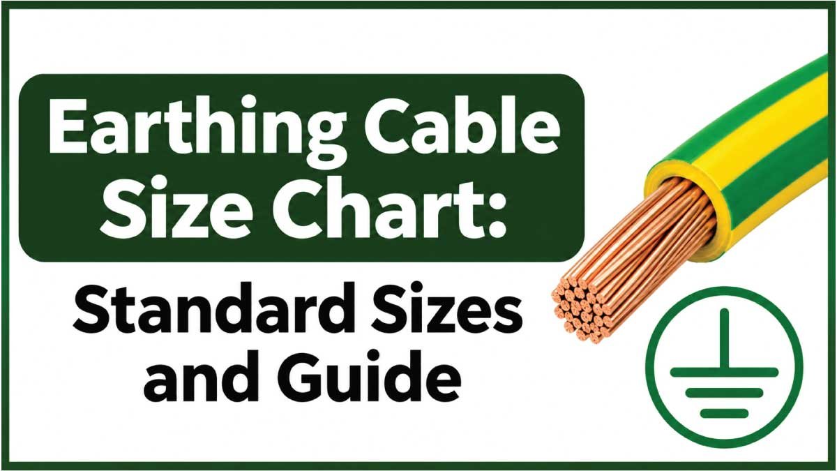
Choosing the correct earthing cable size is essential for protecting electrical installations, equipment, and people from electrical fault hazards. An appropriately sized earthing conductor provides a reliable path for fault current, helping protective devices disconnect the electrical supply when a dangerous fault occurs.
The Earthing Cable Size Chart provides useful information about conductor cross-sectional areas, copper and aluminum wire sizes, IEC sizing requirements, and common electrical applications. Whether you are working on residential wiring, commercial buildings, industrial equipment, or solar installations, understanding earthing cable measurements helps you make informed sizing decisions.
In this complete guide, you will learn about standard earthing cable sizes, protective earthing conductors, bonding cables, fault-current calculations, and the factors that determine the correct conductor size for a safe and reliable electrical installation.
What Is an Earthing Cable?
An earthing cable is an electrical conductor that connects electrical equipment, exposed metal parts, or an electrical installation to the earthing system. Its primary purpose is to provide a safe path for fault current so that protective devices can disconnect the electrical supply when an earth fault occurs.
An earthing cable size chart helps electricians, electrical engineers, contractors, and homeowners understand the conductor sizes used in different electrical installations. It provides information about cross-sectional area, conductor material, applications, and important sizing considerations.
Selecting the correct earthing cable size is essential for electrical safety. An undersized conductor may overheat or become damaged during an electrical fault. An appropriately selected conductor helps maintain a reliable protective connection and supports the operation of circuit breakers, fuses, and other protective devices.
Earthing cable sizing depends on several factors, including the size of the associated phase conductor, prospective fault current, protective device disconnection time, conductor material, installation method, and applicable electrical standards.
This guide explains common earthing cable sizes, copper and aluminum conductors, protective conductor sizing methods, applications, and how to select an appropriate cable for different electrical systems.
Earthing Cable Size Chart
Earthing conductors are available in different cross-sectional areas depending on the electrical installation and protective requirements.
The following chart presents a practical reference based on the IEC 60364 simplified method for protective earthing conductors made from the same material as the associated line conductors.
Standard Earthing Cable Size Chart
| Phase Conductor Size (mm²) | Minimum Copper Earth Conductor (mm²) | Sizing Relationship |
|---|---|---|
| 1.5 | 1.5 | Same size |
| 2.5 | 2.5 | Same size |
| 4 | 4 | Same size |
| 6 | 6 | Same size |
| 10 | 10 | Same size |
| 16 | 16 | Same size |
| 25 | 16 | Fixed minimum |
| 35 | 16 | Fixed minimum |
| 50 | 25 | Half the phase conductor |
| 70 | 35 | Half the phase conductor |
| 95 | 47.5 | Half the phase conductor |
| 120 | 60 | Half the phase conductor |
| 150 | 75 | Half the phase conductor |
| 185 | 92.5 | Half the phase conductor |
| 240 | 120 | Half the phase conductor |
| 300 | 150 | Half the phase conductor |
| 400 | 200 | Half the phase conductor |
Important: This is a simplified reference for protective conductors under the IEC 60364 sizing method, not a universal earthing cable chart. The actual conductor must satisfy fault-current withstand, disconnection-time, mechanical protection, and applicable national code requirements. The final size may need to be larger.
How to Read an Earthing Cable Size Chart
An earthing cable chart relates the size of a protective conductor to the associated phase conductor.
For example:
- 2.5 mm² phase conductor: The simplified method gives a 2.5 mm² copper protective conductor.
- 6 mm² phase conductor: The corresponding protective conductor is 6 mm² copper.
- 16 mm² phase conductor: The corresponding protective conductor is 16 mm² copper.
- 25 mm² phase conductor: The simplified method gives a 16 mm² copper protective conductor.
- 50 mm² phase conductor: The simplified method gives a 25 mm² copper protective conductor.
These relationships apply when the phase and protective conductors use the same material.
When different conductor materials are used, the appropriate material correction factors must be considered.
Understanding Earthing Cable Measurements
Earthing cable sizes are generally expressed in square millimeters (mm²). This measurement describes the cross-sectional area of the conductive material inside the cable.
Understanding the different measurements helps identify the correct conductor for an electrical installation.
Cross-Sectional Area
Cross-sectional area represents the amount of conductive material available to carry electrical current.
Common earthing conductor sizes include:
- 1.5 mm²
- 2.5 mm²
- 4 mm²
- 6 mm²
- 10 mm²
- 16 mm²
- 25 mm²
- 35 mm²
- 50 mm²
- 70 mm²
- 95 mm²
- 120 mm²
A larger cross-sectional area generally provides greater current-carrying capability and lower electrical resistance when comparing conductors of the same material.
However, earthing conductors are primarily selected according to their ability to withstand fault conditions and satisfy protective requirements, not simply their normal operating current.
Cable Diameter
Cable diameter refers to the physical thickness of the conductor or the complete insulated cable.
These are different measurements.
For example, a 6 mm² copper conductor does not have a diameter of 6 mm. Its nominal equivalent solid-conductor diameter is approximately 2.76 mm.
Stranded conductors may have different physical dimensions because of their construction.
The insulation also increases the overall cable diameter.
Electrical Resistance
Electrical resistance describes how strongly a conductor opposes the flow of current.
Copper earthing conductors generally have lower resistance than aluminum conductors of the same cross-sectional area.
Lower resistance helps reduce voltage drop and contributes to the effectiveness of an earth-fault current path.
The actual resistance depends on conductor material, temperature, length, and construction.
Different Types of Earthing Conductors
The term earthing cable can describe several different conductors within an electrical installation. Understanding their functions is important because their sizing requirements are not always the same.
Protective Earthing Conductor (PE)
A protective earthing conductor connects exposed conductive parts of electrical equipment to the protective earthing system.
Its main function is to provide a low-impedance path for fault current.
Examples include:
- Metal electrical enclosures.
- Distribution boards.
- Industrial machinery.
- Metal-bodied appliances.
- Electrical control panels.
- Motor frames.
The PE conductor helps protective devices disconnect the supply when a dangerous fault occurs.
Main Earthing Conductor
The main earthing conductor connects the installation’s main earthing terminal to the earthing arrangement or electrode system, depending on the electrical system design.
It forms an important part of the overall protective earthing installation.
Its size must comply with the applicable earthing standard and the requirements for the specific supply arrangement.
Main Protective Bonding Conductor
A protective bonding conductor connects qualifying extraneous conductive parts to the main earthing terminal.
Its purpose is to reduce dangerous potential differences between conductive parts during fault conditions.
Examples may include:
- Metallic water service pipes.
- Structural metallic components.
- Other qualifying metallic services.
Bonding conductors have their own sizing requirements and should not automatically be sized using the protective earthing conductor chart.
Earth Electrode Conductor
An earth electrode conductor connects an earth electrode, such as an earth rod or earth plate, to the earthing terminal or associated earthing arrangement.
Common electrode arrangements include:
- Copper-bonded earth rods.
- Copper earth plates.
- Buried copper conductors.
- Earth electrode networks.
- Foundation earthing systems.
The required conductor size depends on the applicable electrode and installation requirements, mechanical protection, corrosion considerations, and fault-current conditions.
Copper vs. Aluminum Earthing Cables
Copper and aluminum are two materials used in electrical conductors. However, their electrical and physical characteristics differ.
Choosing the correct material is important for maintaining a reliable protective connection.
Copper Earthing Cable
Copper is widely used for protective earthing because of its electrical conductivity, mechanical properties, and availability in different conductor sizes.
Its advantages include:
- High electrical conductivity.
- Lower resistance than aluminum at equal cross-sectional area.
- Good mechanical strength.
- Availability in solid and stranded constructions.
- Suitability for many electrical earthing applications.
Copper conductors are frequently used in residential, commercial, and industrial installations.
Aluminum Earthing Cable
Aluminum is used in certain electrical installations, particularly larger distribution systems.
Its main advantages include:
- Lower weight than copper.
- Lower material cost in many markets.
- Good conductivity relative to its weight.
- Availability in larger conductor sizes.
However, aluminum requires suitable terminals, connectors, and installation practices.
Its higher resistance compared with copper at the same cross-sectional area must also be considered when calculating protective conductor size.
Copper vs. Aluminum Comparison Chart
| Characteristic | Copper | Aluminum |
|---|---|---|
| Electrical conductivity | Higher | Lower |
| Weight | Heavier | Lighter |
| Resistance at equal area | Lower | Higher |
| Mechanical strength | Generally higher | Generally lower |
| Corrosion considerations | Depends on environment | Requires suitable protection and connections |
| Common applications | Protective and bonding conductors | Selected larger electrical installations |
Copper and aluminum earthing conductors should not be considered interchangeable based only on their cross-sectional areas.
The material correction factors and applicable installation standards must be checked before selecting an alternative conductor.
Read Latest Guide:
Earthing Cable Size Selection According to IEC Standards
IEC 60364-5-54 provides requirements for earthing arrangements and protective conductors.
Under its simplified selection method, the minimum protective conductor cross-sectional area is related to the associated phase conductor size when both conductors use the same material.
IEC Protective Conductor Sizing Table
| Phase Conductor Cross-Section (S) | Minimum PE Conductor Cross-Section |
|---|---|
| S ≤ 16 mm² | S |
| 16 mm² < S ≤ 35 mm² | 16 mm² |
| S > 35 mm² | S/2 |
This method provides a convenient way to determine a preliminary protective conductor size.
For example:
If the phase conductor is 10 mm², the protective conductor is selected as 10 mm².
If the phase conductor is 25 mm², the simplified method gives 16 mm².
If the phase conductor is 70 mm², the simplified method gives 35 mm².
Minimum Size for Separate Protective Conductors
IEC 60364 also specifies minimum cross-sectional areas for protective conductors that do not form part of a cable or share a common enclosure with the line conductor.
The commonly referenced minimums are:
| Installation Condition | Copper PE Conductor | Aluminum PE Conductor |
|---|---|---|
| Mechanically protected | 2.5 mm² | 16 mm² |
| Not mechanically protected | 4 mm² | 16 mm² |
These minimums do not replace the fault-current calculation or other applicable requirements.
Adiabatic Method for Earthing Cable Sizing
Another method of determining protective conductor size is the adiabatic equation.
It calculates the minimum conductor cross-sectional area needed to withstand the thermal effects of an electrical fault until the protective device disconnects the supply.
The equation is:
S = √(I² × t) / k
Where:
- S = Required conductor cross-sectional area in mm².
- I = Prospective fault current in amperes.
- t = Protective device operating time in seconds.
- k = Material and temperature-dependent factor.
The value of k depends on the conductor material, insulation, initial temperature, and permitted final temperature.
For example, the calculation requires the expected fault current and the actual disconnection time of the protective device. Without these values, a reliable conductor size cannot be calculated.
If the calculated size falls between standard conductor sizes, the next larger suitable standard size is selected.
Read Latest Guide:
Common Applications of Earthing Cable Sizes
Earthing conductors are used in many types of electrical installations. Their sizes depend on the system design and protective requirements.
Residential Electrical Installations
Residential earthing systems protect electrical equipment, distribution boards, and other exposed conductive parts.
Common conductor sizes encountered in residential installations include:
- 2.5 mm² for certain mechanically protected protective conductor arrangements.
- 4 mm² for certain unprotected separate protective conductors.
- 6 mm² for selected protective and earthing applications.
- 10 mm² and 16 mm² for larger protective connections, depending on design.
These are examples of commonly encountered sizes, not universal residential requirements.
Commercial Buildings
Commercial electrical installations may require larger protective conductors because of their electrical loads and distribution arrangements.
Applications include:
- Main distribution boards.
- Electrical panels.
- HVAC equipment.
- Commercial lighting systems.
- Elevators.
- Electrical machinery.
The conductor size must be coordinated with the phase conductors, fault protection, and installation conditions.
Industrial Earthing Systems
Industrial installations frequently use substantial earthing conductors to protect machinery, motors, switchgear, and distribution equipment.
Commonly encountered conductor sizes include 16 mm², 25 mm², 35 mm², 50 mm², 70 mm², and larger.
The appropriate size depends on the prospective fault current, protective device characteristics, equipment requirements, and applicable industrial standards.
Solar Power Systems
Solar installations include protective earthing connections for inverters, metal mounting structures, electrical enclosures, and other exposed conductive parts where required.
The conductor size depends on the equipment instructions, electrical design, fault protection, and applicable photovoltaic installation standards.
DC circuit earthing and AC protective earthing requirements must be evaluated separately where applicable.
Read Latest Guide:
How to Choose the Correct Earthing Cable Size
Selecting an appropriate earthing cable requires evaluating the electrical installation rather than choosing a size based on a general chart alone.
1. Identify the Earthing Conductor Type
First, determine which conductor you need.
It may be:
- A protective earthing conductor.
- A main earthing conductor.
- A protective bonding conductor.
- An earth electrode conductor.
Each has different functions and may have different sizing requirements.
2. Check the Phase Conductor Size
For a protective conductor selected using the IEC simplified method, identify the cross-sectional area of the associated phase conductor.
Use the relevant sizing relationship to determine the preliminary protective conductor size.
3. Determine the Prospective Fault Current
The conductor must withstand the thermal effects of the expected earth-fault current.
The prospective fault current depends on the electrical system, supply characteristics, and earth-fault loop impedance.
4. Check the Protective Device
Identify the protective device used in the circuit.
Its operating characteristics determine how quickly it disconnects the supply during a fault.
A conductor must withstand the fault current for the required disconnection period.
5. Consider the Installation Environment
Environmental and mechanical conditions can affect the selection.
Consider:
- Indoor or outdoor installation.
- Exposure to moisture.
- Chemical exposure.
- Mechanical damage.
- Ambient temperature.
- Corrosion risks.
- Conduit or cable enclosure arrangements.
6. Verify Applicable Electrical Standards
Finally, confirm the selected conductor against the relevant electrical regulations and manufacturer requirements.
Different countries may use different standards and minimum conductor requirements.
A chart should be treated as a design reference rather than a substitute for electrical calculations and inspection.
Common Earthing Cable Sizing Mistakes
Incorrect earthing conductor selection can reduce the effectiveness of an electrical protection system.
Avoid these common mistakes:
- Using an undersized conductor: A small conductor may not withstand the thermal effects of an earth fault.
- Confusing earthing and bonding: These conductors have different functions and sizing requirements.
- Ignoring conductor material: Copper and aluminum have different electrical properties.
- Ignoring mechanical protection: Separate protective conductors may have minimum size requirements based on their protection.
- Using the phase conductor size without checking the standard: The required protective conductor size depends on the applicable sizing method.
- Ignoring fault-current calculations: A conductor must withstand the expected fault current until disconnection.
- Overlooking corrosion: Outdoor and buried earthing connections require suitable materials and corrosion protection.
- Assuming all earth conductors are interchangeable: PE conductors, bonding conductors, and electrode conductors have different purposes.
Frequently Asked Questions About Earthing Cable Sizes
1. What Is the Standard Earthing Cable Size?
There is no single standard size suitable for every installation. The required size depends on the conductor type, associated phase conductor, fault current, protective device, installation conditions, and applicable electrical standard.
2. What Size Earth Cable Is Required for a 2.5 mm² Wire?
Under the IEC simplified method, a 2.5 mm² copper phase conductor corresponds to a 2.5 mm² copper protective conductor, provided the relevant conditions are satisfied.
3. What Size Earth Cable Is Required for a 6 mm² Wire?
The IEC simplified method gives a 6 mm² protective conductor when the associated phase conductor is 6 mm² and both use the same material. The final selection must also satisfy fault-current and installation requirements.
4. What Size Earth Cable Is Required for a 10 mm² Wire?
Under the simplified IEC method, a 10 mm² copper phase conductor corresponds to a 10 mm² copper protective conductor.
5. Is a 4 mm² Earth Cable Enough?
A 4 mm² earth conductor may be suitable for certain installations, but it is not universally sufficient. Its suitability depends on the conductor function, fault current, disconnection time, mechanical protection, and applicable regulations.
6. Is Copper Better Than Aluminum for Earthing?
Copper generally offers higher electrical conductivity and lower resistance for the same cross-sectional area. Aluminum is lighter but requires suitable sizing, compatible connections, and appropriate installation practices.
7. What Is the Difference Between an Earthing Cable and a Bonding Cable?
An earthing conductor connects parts of an electrical installation to the earthing arrangement. A bonding conductor connects qualifying conductive parts to help reduce dangerous potential differences. Both contribute to electrical safety but have different functions.
8. Can I Use the Same Size Cable for Phase and Earth?
Sometimes. Under the IEC simplified method, a protective conductor is generally the same size as the phase conductor when the phase conductor is 16 mm² or smaller and both use the same material. Larger phase conductors may use different protective conductor sizes under the applicable method.
9. Does Earthing Cable Size Depend on Cable Length?
The required conductor size is primarily determined by fault-current withstand, disconnection requirements, and applicable installation rules. However, conductor length affects impedance and can influence the effectiveness of the earth-fault protection system.
10. Which Standard Is Used for Earthing Cable Sizing?
IEC 60364-5-54 provides internationally used requirements for earthing arrangements and protective conductors. Other installations may follow BS 7671, NEC, or national electrical regulations, depending on their location and application.
Conclusion
The earthing cable size chart is an important reference for selecting protective conductors in residential, commercial, and industrial electrical installations.
The correct conductor size depends on its function, associated phase conductor, material, prospective fault current, protective device operating time, and installation conditions.
The IEC simplified sizing method provides a useful starting point for protective earthing conductor selection, but it does not replace fault-current calculations or local electrical requirements.
Always verify the final earthing cable size against the applicable electrical standard and manufacturer specifications. Correct conductor selection helps maintain reliable fault protection and improves the overall safety of an electrical installation.