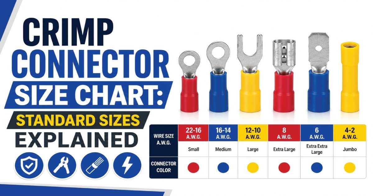
A crimp connector size chart helps identify the correct connector for different wire sizes, conductor types, terminal dimensions, and electrical applications. Crimp connectors are widely used in automotive wiring, control panels, appliances, electronics, batteries, and industrial systems.
Choosing the correct crimp connector requires matching the wire gauge, conductor size, connector type, insulation, terminal size, and application. A properly crimped connection provides reliable electrical contact and strong mechanical retention.
What Is a Crimp Connector?
A crimp connector is an electrical terminal or connector that joins a wire to another wire, terminal, or electrical component by mechanically compressing the connector around the conductor.
Crimp connectors are commonly used for:
- Automotive wiring
- Battery connections
- Electrical panels
- Control circuits
- Appliances
- Industrial machinery
- Marine wiring
- Electronics
- Lighting systems
- Grounding connections
Unlike soldered connections, crimp connectors rely on controlled mechanical compression to establish the electrical and mechanical connection.
How Does a Crimp Connector Work?
A crimp connector works by compressing its metal barrel around a stripped conductor. The compression creates contact between the conductor and connector while mechanically securing the wire.
A typical installation involves:
- Selecting the correct connector.
- Stripping the wire to the specified length.
- Inserting the conductor fully.
- Positioning the connector in the crimp tool.
- Applying the correct crimp force.
- Inspecting the finished connection.
Correct crimping is essential for maintaining reliable electrical performance.
Crimp Connector Size Chart
Crimp connectors are available for different wire sizes and terminal configurations. The following chart provides general reference ranges for common electrical and automotive applications.
| Wire Size | Approx. AWG | Common Connector Type | Typical Application |
|---|---|---|---|
| 0.5 mm² | 20 AWG | Small insulated | Electronics |
| 0.75 mm² | 18 AWG | Insulated terminal | Control wiring |
| 1.0 mm² | 17 AWG | Insulated terminal | Electrical circuits |
| 1.5 mm² | 16 AWG | Butt/ring/spade | Automotive |
| 2.5 mm² | 14 AWG | Butt/ring/spade | General wiring |
| 4 mm² | 12 AWG | Heavy-duty terminal | Power circuits |
| 6 mm² | 10 AWG | Heavy-duty terminal | Battery wiring |
| 10 mm² | 8 AWG | Power lug | High-current systems |
| 16 mm² | 6 AWG | Heavy-duty lug | Battery/power |
| 25 mm² | 4 AWG | Compression lug | High-current systems |
| 35 mm² | 2 AWG | Large power lug | Industrial |
| 50 mm² | 1/0 AWG | Heavy-duty lug | Power distribution |
Exact connector dimensions and wire ranges vary by manufacturer and product series.
Crimp Connector Size by Wire Gauge
Wire gauge is one of the most important specifications when selecting a crimp connector. The connector barrel must be designed for the conductor size so that the crimp produces the required mechanical and electrical connection.
Common AWG sizes include:
- 22 AWG
- 20 AWG
- 18 AWG
- 16 AWG
- 14 AWG
- 12 AWG
- 10 AWG
- 8 AWG
- 6 AWG
- 4 AWG
- 2 AWG
- 1/0 AWG
Always check the connector’s approved wire range before installation.
Crimp Connector Size by Metric Wire Size
Metric wire sizes are commonly identified by conductor cross-sectional area in square millimeters. Crimp connectors are manufactured for specific conductor ranges that correspond to these sizes.
| Wire Size | Typical Connector Category |
|---|---|
| 0.5 mm² | Small electronics |
| 0.75 mm² | Control wiring |
| 1.0 mm² | Small electrical circuits |
| 1.5 mm² | General wiring |
| 2.5 mm² | Automotive/general |
| 4 mm² | Medium power |
| 6 mm² | Battery/power |
| 10 mm² | High-current |
| 16 mm² | Large power |
| 25 mm² | Battery/distribution |
| 35 mm² | Industrial power |
| 50 mm² | Heavy-duty power |
The connector should be specifically rated for the conductor size.
Types of Crimp Connectors
Crimp connectors are available in different designs depending on whether the connection joins wires, attaches wires to studs, or connects to electrical components.
Common types include:
- Butt connectors
- Ring terminals
- Fork terminals
- Spade terminals
- Pin terminals
- Bullet connectors
- Quick-disconnect terminals
- Blade terminals
- Ferrules
- Parallel connectors
Each type is designed for a particular connection method and application.
Butt Crimp Connectors
Butt connectors are designed to join two wires end-to-end. They contain conductive metal barrels that receive a conductor at each end and are crimped to secure both wires.
Common applications include:
- Automotive repairs
- Wiring extensions
- Appliance wiring
- Control systems
- Lighting
- Marine wiring
Butt connectors are available in different wire-size ranges and insulation styles.
Ring Crimp Terminals
Ring crimp terminals have a circular mounting hole that attaches to a screw, bolt, or stud. They provide strong retention because the terminal surrounds the mounting hardware.
Ring terminals are commonly used for:
- Grounding
- Batteries
- Automotive wiring
- Control panels
- Electrical equipment
- Power connections
The ring-hole size must match the mounting hardware.
Fork Crimp Terminals
Fork terminals, also called spade terminals, have an open-ended connection that can fit under certain screws without completely removing the fastener.
They are commonly used in:
- Control panels
- Switches
- Relays
- Terminal blocks
- Small electrical equipment
Fork terminals are convenient for some installations, but their suitability depends on the terminal design and application.
Spade Crimp Connectors
Spade connectors provide a flat terminal interface and are commonly used with compatible tabs, screws, or electrical components. Their shape makes them useful for compact electrical connections.
Typical applications include:
- Automotive wiring
- Appliances
- Switches
- Relays
- Control panels
- Small motors
Select the spade width and wire range according to the mating terminal.
Bullet Crimp Connectors
Bullet connectors have a cylindrical male or female connection and can be disconnected relatively easily. They are commonly used where removable wiring connections are required.
Typical applications include:
- Automotive wiring
- Motorcycle wiring
- Lighting
- Small electrical equipment
- Hobby electronics
The male and female portions must have compatible dimensions and current ratings.
Blade Crimp Connectors
Blade terminals use a flat metal tab and mating receptacle. They are widely used in automotive and electrical equipment because they provide a convenient disconnectable connection.
Common blade terminal sizes include:
- 2.8 mm
- 4.8 mm
- 6.3 mm
- 9.5 mm
The blade width and terminal thickness must match the corresponding connector.
Quick Disconnect Crimp Connectors
Quick-disconnect terminals allow wires to be connected and disconnected without removing a permanent screw connection. They are commonly available as male and female terminals.
Applications include:
- Automotive wiring
- Appliances
- Control panels
- Electrical equipment
- Relays
- Switches
The terminal must be correctly matched to its mating connector.
Insulated Crimp Connectors
Insulated crimp connectors have a protective covering around the conductive terminal area. The insulation helps reduce the possibility of accidental contact and short circuits.
Common insulation materials include:
- PVC
- Nylon
- Polyolefin
- Heat-shrink materials
When selecting an insulated connector, check its wire range, voltage rating, temperature rating, and environmental suitability.
Non-Insulated Crimp Connectors
Non-insulated crimp connectors consist primarily of a conductive metal terminal without an integrated insulating sleeve. They are often used in professional wiring assemblies and applications where additional insulation is installed separately.
Advantages include:
- Compact design
- Easy visual inspection
- Wide selection of terminal shapes
- Suitable for specialized crimping systems
- Useful in enclosed assemblies
Additional insulation may be necessary depending on the application.
Heat Shrink Crimp Connectors
Heat-shrink crimp connectors combine mechanical crimping with heat-shrink insulation. When properly installed, the outer sleeve can provide additional environmental protection around the connection.
They are commonly used for:
- Automotive wiring
- Marine wiring
- Outdoor equipment
- Battery connections
- Industrial applications
Use the correct heat source and follow the connector manufacturer’s installation instructions.
Crimp Connector Color Coding
Many insulated crimp terminals use color coding to indicate their approximate wire-size range. However, colors are not universal across every manufacturer.
A commonly encountered system is:
| Color | General Wire Range* |
|---|---|
| Red | Small wire |
| Blue | Medium wire |
| Yellow | Larger wire |
*Color ranges vary by manufacturer and standard. Always check the connector packaging or technical documentation.
Crimp Connector Material
Crimp connectors are manufactured from conductive materials selected for electrical conductivity, mechanical strength, and environmental resistance.
Common materials include:
| Material | Common Use |
|---|---|
| Copper | General electrical connections |
| Tinned Copper | Corrosion-resistant applications |
| Brass | Automotive/electrical terminals |
| Aluminum | Specialized power connections |
| Nickel-Plated Materials | Higher-temperature applications |
Material compatibility with the conductor is important when selecting a connector.
Copper Crimp Connectors
Copper crimp connectors provide good electrical conductivity and are widely used for electrical and automotive wiring. They are available in many terminal shapes and conductor-size ranges.
Common applications include:
- Battery wiring
- Grounding
- Control panels
- Automotive systems
- Electrical equipment
- Power connections
The copper connector should be properly matched to the conductor and installation environment.
Tinned Copper Crimp Connectors
Tinned copper connectors have a protective tin coating that can improve resistance to corrosion. They are particularly useful in applications exposed to moisture or humid environments.
Common applications include:
- Marine wiring
- Battery systems
- Outdoor equipment
- Automotive systems
- Industrial machinery
Tinned copper connectors should still be correctly crimped and protected according to the application.
Also Read: AWG Wire Size Chart: Gauge, Ampacity & Uses
Crimp Connector Current Rating
The current rating of a crimp connector depends on its conductor size, metal construction, contact area, temperature rating, and design. A connector should not be selected based solely on physical size.
Consider:
- Wire size
- Connector material
- Contact area
- Continuous current
- Temperature
- Installation environment
- Manufacturer rating
The connector should be rated for the electrical load of the circuit.
How to Choose the Correct Crimp Connector
Selecting the correct crimp connector requires matching the wire, connector type, terminal dimensions, current, and application.
Follow these steps:
- Identify the wire gauge.
- Determine metric wire size if applicable.
- Select the connector type.
- Check the terminal dimensions.
- Match the conductor material.
- Verify current rating.
- Check insulation requirements.
- Select the correct crimp tool.
- Verify temperature and environmental ratings.
- Follow manufacturer instructions.
Common Crimp Connector Sizing Mistakes
Incorrect connector selection can result in loose wires, increased resistance, overheating, and connection failure.
Avoid:
- Using the wrong wire range
- Selecting by color alone
- Using an oversized connector
- Using an undersized connector
- Cutting conductor strands
- Using the wrong crimp tool
- Under-crimping
- Over-crimping
- Ignoring current ratings
- Mixing incompatible connector materials
Key Points to Remember
A crimp connector size chart is useful for identifying compatible wire sizes and connector types, but proper selection requires checking the complete connector specification.
Always remember:
- Match connector and wire size.
- Select the correct connector type.
- Check conductor material.
- Verify current capacity.
- Choose appropriate insulation.
- Use the correct crimp tool.
- Follow the specified crimping procedure.
- Inspect the finished connection.
- Consider temperature and environmental conditions.
- Follow manufacturer specifications.
Crimp Connector Size for Different Applications
Crimp connectors are used in automotive, marine, battery, industrial, electronic, and household wiring. The correct connector depends on wire size, connector design, current capacity, terminal dimensions, insulation, and environmental conditions.
| Application | Common Crimp Connector | Typical Wire Range* |
|---|---|---|
| Automotive Wiring | Butt/Blade/Ring | 0.5–10 mm² |
| Battery Wiring | Heavy-Duty Lug | 6–50 mm² |
| Grounding | Ring Terminal | 1.5–50 mm² |
| Control Panels | Ring/Spade | 0.5–6 mm² |
| Marine Wiring | Tinned Copper | 0.5–25 mm² |
| Appliance Wiring | Quick Disconnect | 0.75–6 mm² |
| Solar Wiring | Ring/Butt | 2.5–16 mm² |
| Motor Wiring | Heavy-Duty Terminal | 4–50 mm² |
| Industrial Equipment | Compression Connector | 6–120 mm² |
These are general reference ranges. Actual connector selection depends on the manufacturer’s specifications, conductor type, current, temperature, and application.
Also Read: Copper Wire Size Chart: AWG & mm² Guide for Projects
Crimp Connector for Automotive Wiring
Automotive electrical systems use many types of crimp connectors because vehicles contain numerous wires, sensors, switches, relays, lights, and control modules. Proper terminal selection helps maintain reliable connections despite vibration and temperature changes.
Common automotive crimp connectors include:
- Ring terminals
- Butt connectors
- Blade terminals
- Bullet connectors
- Spade terminals
- Quick-disconnect terminals
Choose a connector based on wire gauge, terminal type, current, and environmental conditions.
Crimp Connector for Battery Cables
Battery cables can carry high current, requiring heavy-duty crimp connectors capable of handling substantial electrical and mechanical loads. Larger battery cables generally require copper or tinned copper compression-style connectors.
Before selecting a battery connector, check:
- Cable cross-sectional area
- Battery terminal size
- Connector material
- Current capacity
- Crimping method
- Environmental conditions
- Corrosion resistance
The connector must provide a secure connection without damaging the conductor.
Crimp Connector for Ground Wires
Ground wires require reliable connections to equipment frames, chassis points, grounding bars, or electrical terminals. Ring crimp terminals are commonly used because their closed design provides good mechanical retention.
For grounding connections:
- Match the connector to the wire.
- Verify the mounting-hole size.
- Use compatible materials.
- Ensure good contact.
- Crimp with the correct tool.
- Follow applicable electrical requirements.
A loose grounding connection can compromise the intended protection of the electrical system.
Crimp Connector for Solar Wiring
Crimp connectors can be used in suitable solar applications for battery wiring, grounding, control wiring, and equipment connections. Outdoor solar installations require connectors that can withstand temperature changes, moisture, and environmental exposure.
Check:
- Cable size
- Connector material
- Current rating
- Temperature rating
- Terminal dimensions
- Environmental requirements
- Equipment specifications
Only use connectors approved for the specific solar equipment and wiring method.
Crimp Connector for Marine Wiring
Marine wiring is exposed to moisture, salt, vibration, and corrosion. Tinned copper crimp connectors are commonly used because the tin coating can improve corrosion resistance.
For marine installations, consider:
- Tinned copper construction
- Correct wire size
- Heat-shrink protection
- Waterproof connection where required
- Proper crimping
- Corrosion-resistant hardware
- Environmental rating
The connector and insulation system should be suitable for the marine environment.
Also Read: Solar Cable Size Chart: Choose the Right Cable Size
Crimp Connector for Control Panels
Control panels often contain low-current circuits for switches, sensors, relays, contactors, indicators, and controllers. Small insulated crimp terminals are commonly used where the panel design permits them.
Typical terminal choices include:
- Ring terminals
- Fork terminals
- Spade terminals
- Pin terminals
- Ferrules
Always match the connector to the wire size and terminal configuration.
Crimp Connector for Appliances
Appliances commonly use blade, spade, ring, and quick-disconnect terminals. These connectors provide convenient assembly and maintenance while maintaining a reliable connection when correctly installed.
Before selecting an appliance connector, consider:
- Wire gauge
- Terminal width
- Current
- Temperature
- Insulation
- Mating terminal
- Manufacturer requirements
High-temperature appliances may require terminals specifically rated for elevated temperatures.
Crimp Connector for Motors
Motor connections can experience vibration, heat, and starting currents. Crimp connectors used on motor wiring should therefore be suitable for the electrical and mechanical conditions of the installation.
Consider:
- Motor current
- Wire size
- Terminal configuration
- Connector material
- Temperature rating
- Vibration
- Crimping method
The connector should be installed securely and protected from mechanical stress.
Crimp Connector for Generators
Generators can produce high output currents, requiring appropriately rated cable terminations. Large generator connections may use compression lugs or heavy-duty crimp connectors.
Check:
- Generator output
- Cable size
- Conductor material
- Terminal stud size
- Connector current rating
- Temperature rating
- Short-circuit requirements
Large power connections should follow the generator manufacturer’s installation specifications.
Crimp Connector for Inverters
Inverters can carry substantial DC or AC current, especially in battery and solar systems. The crimp connector must match the cable and inverter terminal specifications.
Important factors include:
- Maximum current
- Cable size
- DC or AC circuit
- Terminal size
- Connector material
- Temperature rating
- Manufacturer requirements
A properly installed connection helps minimize contact resistance and unwanted heating.
Crimp Connector Wire Size
The wire size must fall within the connector manufacturer’s approved range. A connector that physically accepts a wire may still be electrically unsuitable if the conductor is outside its rated range.
| Wire Size | Approx. AWG | Common Connector Applications |
|---|---|---|
| 0.5 mm² | 20 AWG | Electronics |
| 0.75 mm² | 18 AWG | Control wiring |
| 1.0 mm² | 17 AWG | Small circuits |
| 1.5 mm² | 16 AWG | Automotive |
| 2.5 mm² | 14 AWG | General wiring |
| 4 mm² | 12 AWG | Power circuits |
| 6 mm² | 10 AWG | Battery |
| 10 mm² | 8 AWG | High current |
| 16 mm² | 6 AWG | Power/battery |
| 25 mm² | 4 AWG | High current |
Crimp Connector Color Code
Many insulated crimp terminals use colors to indicate the approximate wire-size range. However, color coding can vary between manufacturers and terminal standards.
A common system is:
| Color | General Wire Range |
|---|---|
| Red | Small wire |
| Blue | Medium wire |
| Yellow | Larger wire |
Always verify the actual wire range printed on the packaging because color alone is not a reliable universal sizing system.
Crimp Connector Terminal Width
For blade, spade, and quick-disconnect connectors, terminal width is an important dimension. The connector must fit the corresponding male or female terminal correctly.
Common blade widths include:
- 2.8 mm
- 4.8 mm
- 6.3 mm
- 9.5 mm
The terminal thickness and mating configuration should also be checked before installation.
Crimp Connector Insulation Types
Crimp connectors are available with different insulation materials and designs. The correct insulation depends on temperature, voltage, environmental conditions, and application.
| Insulation | General Application |
|---|---|
| PVC | General wiring |
| Nylon | Automotive/control |
| Polyolefin | Heat-shrink applications |
| Heat Shrink | Moisture protection |
| Non-Insulated | Specialized assemblies |
Check the connector manufacturer’s temperature and voltage specifications before installation.
Heat Shrink Crimp Connectors
Heat-shrink crimp connectors provide mechanical crimping along with additional insulation and environmental protection. They are useful where moisture, vibration, or contamination could affect an exposed connection.
Common applications include:
- Marine wiring
- Automotive wiring
- Battery systems
- Outdoor equipment
- Industrial machinery
The connector must be crimped correctly before applying heat to shrink the outer sleeve.
Waterproof Crimp Connectors
Water-resistant or sealed crimp connectors are designed for applications where moisture protection is important. Some use heat-shrink tubing with adhesive, while others use dedicated sealed connector housings.
Potential applications include:
- Marine systems
- Outdoor lighting
- Automotive wiring
- Agricultural equipment
- Outdoor machinery
The complete connection system must be suitable for the required environmental protection level.
Crimp Connector Current Rating
Current capacity depends on the connector’s metal construction, conductor size, contact area, temperature rating, and design. A physically larger connector does not automatically have a higher current rating.
Consider:
- Wire gauge
- Connector material
- Contact area
- Continuous current
- Ambient temperature
- Connection quality
- Manufacturer rating
Always use the manufacturer’s published electrical ratings where available.
Crimp Connector Voltage Rating
The voltage rating identifies the electrical voltage for which the connector is designed under specified conditions. Insulation, terminal spacing, and connector construction all influence voltage suitability.
Before selecting a connector, verify:
- System voltage
- Connector voltage rating
- Insulation rating
- Temperature rating
- Environmental conditions
- Applicable standards
Never assume that a connector is suitable for a particular voltage simply because it physically fits.
Crimping Tool Size
The crimping tool must match the connector type and wire range. Different connectors require different die shapes and compression profiles.
Common crimping tools include:
- Hand crimpers
- Ratchet crimpers
- Hydraulic crimpers
- Battery-powered crimpers
- Specialized terminal crimpers
For large power connectors, follow the connector manufacturer’s specified tooling and die requirements.
How to Crimp a Connector Correctly
A proper crimp requires correct wire preparation, connector positioning, and tool selection. The conductor should be fully inserted and compressed according to the connector manufacturer’s specifications.
Basic procedure:
- Select the correct connector.
- Strip the wire to the specified length.
- Avoid cutting conductor strands.
- Insert the wire completely.
- Position the connector correctly.
- Use the correct crimp die.
- Apply the required crimp.
- Inspect the connection.
- Perform an appropriate mechanical check.
How to Test a Crimp Connection
A finished crimp should be inspected before the circuit is energized. Visual inspection can identify many installation problems, while electrical and mechanical testing may be appropriate for critical applications.
Check for:
- Fully inserted conductor
- Correct crimp position
- No loose strands
- No damaged insulation
- Proper terminal deformation
- Secure mechanical connection
- Good electrical continuity
For critical systems, follow the applicable testing procedure or manufacturer requirements.
Crimp Connector vs Solder Connection
Crimping and soldering are different wire-termination methods. A crimp connector uses controlled mechanical compression, while soldering uses molten solder to create the connection.
| Feature | Crimp Connection | Solder Connection |
|---|---|---|
| Installation | Mechanical | Thermal |
| Tool | Crimping tool | Soldering equipment |
| Speed | Generally fast | Generally slower |
| Field repair | Convenient | Requires equipment |
| Vibration performance | Depends on crimp quality | Depends on joint design |
| Consistency | High with correct tooling | Depends on technique |
The appropriate method depends on the equipment design and applicable standards.
How to Choose the Correct Crimp Connector
Selecting the correct crimp connector involves more than matching the wire size. The connector must also match the terminal, current, voltage, environment, and installation method.
Use this checklist:
- Identify wire gauge.
- Determine metric conductor size.
- Select connector type.
- Check terminal dimensions.
- Verify current rating.
- Verify voltage rating.
- Choose suitable insulation.
- Check temperature rating.
- Select correct crimping tool.
- Follow manufacturer instructions.
Common Crimp Connector Installation Mistakes
Poor connector installation can cause high resistance, intermittent faults, overheating, and premature failure. Most problems can be avoided by using the correct connector and proper crimping procedure.
Avoid:
- Using the wrong connector size
- Choosing by color only
- Cutting conductor strands
- Incorrect stripping length
- Using the wrong crimp die
- Under-crimping
- Over-crimping
- Pulling the wire excessively
- Ignoring environmental ratings
- Reusing damaged connectors
FAQs:
How do I know what size crimp connector I need?
Select a crimp connector based on the wire gauge or cross-sectional area, connector type, and electrical application. The connector should also match the required terminal dimensions, current rating, insulation requirements, and manufacturer specifications.
What color crimp connector is used for 14 AWG wire?
Blue is commonly associated with a medium wire-size range that can include 14 AWG in many insulated terminal systems. However, color coding varies, so always verify the manufacturer’s stated wire range before making a connection.
Can I crimp different wire sizes together?
Some specialized connectors are designed to accommodate a specified range of conductor sizes, but ordinary crimp connectors should not be assumed to accept different wire sizes. Always use a connector specifically rated for the conductors being joined.
Are crimp connectors better than solder?
Crimp connectors can provide highly reliable connections when the correct connector and tooling are used. They are also convenient for field installation. Whether crimping or soldering is preferable depends on the application, equipment specifications, environmental conditions, and applicable standards.
Can I reuse a crimp connector?
Crimp connectors are generally intended for one-time installation. Removing a crimped terminal can deform the connector or damage the conductor. For reliable connections, use a new connector rather than reusing a previously crimped terminal.
Final Thoughts
A crimp connector size chart provides a useful starting point for selecting connectors according to wire size and application. However, reliable termination requires checking connector type, wire range, current rating, voltage rating, insulation, and tooling.
Before installing a crimp connector:
- Match the connector to the wire.
- Select the correct terminal style.
- Verify current and voltage ratings.
- Check insulation requirements.
- Use the correct crimping tool.
- Follow the specified crimp procedure.
- Inspect the completed connection.
- Consider temperature and environmental conditions.
- Avoid reusing damaged connectors.
- Follow manufacturer specifications and applicable electrical standards.
A properly selected and crimped connector provides a secure electrical and mechanical connection for automotive, industrial, marine, battery, control, and general wiring applications.