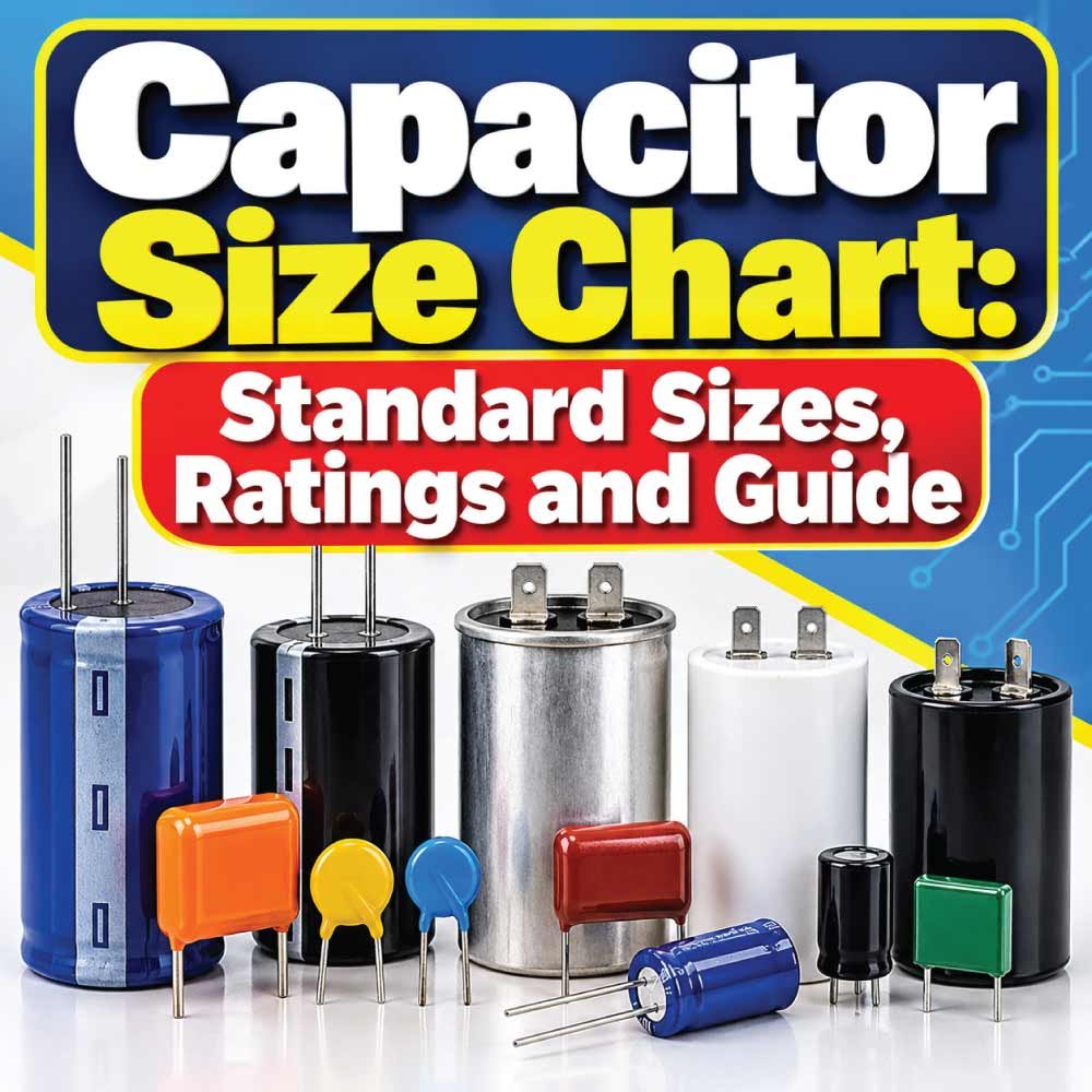
Choosing the right capacitor requires more than matching a capacitance number. Capacitor size can refer to electrical capacitance, voltage rating, physical dimensions, package style, or lead spacing, depending on the application. A capacitor may have the correct capacitance but still be unsuitable because its voltage rating, temperature characteristics, polarity, or physical size does not match the circuit.
This Capacitor Size Chart explains the most important capacitor measurements, common capacitance values, voltage ratings, physical size considerations, capacitor types, and selection factors. It also explains how to read capacitor markings and how to choose a suitable replacement without relying on physical size alone.
What Is Capacitor Size?
Capacitor size has several meanings in electrical work. The most important electrical measurement is capacitance, expressed in farads (F), but practical capacitors are commonly rated in microfarads (µF), nanofarads (nF), or picofarads (pF).
Physical dimensions are also important. Two capacitors can have the same capacitance and voltage rating while having very different body dimensions because they use different technologies, materials, package designs, or manufacturers.
When selecting a capacitor, consider:
- Capacitance value
- Voltage rating
- Capacitor type
- Physical dimensions
- Lead spacing or terminal arrangement
- Polarity
- Temperature rating
- Tolerance
- Frequency and application requirements
Therefore, a capacitor size chart should be used as a starting point rather than treating physical dimensions as a universal electrical standard.
Capacitor Size Chart by Capacitance
Capacitance describes how much electrical charge a capacitor can store relative to voltage. Common capacitor values range from very small picofarad values to large microfarad values used in power and motor applications.
The following chart shows commonly encountered nominal capacitance values.
| Capacitance | Equivalent Value | Common Usage Examples |
|---|---|---|
| 10 pF | 0.01 nF | RF and high-frequency circuits |
| 22 pF | 0.022 nF | Oscillator and timing circuits |
| 47 pF | 0.047 nF | High-frequency applications |
| 100 pF | 0.1 nF | Signal and RF circuits |
| 220 pF | 0.22 nF | Filtering and timing |
| 470 pF | 0.47 nF | Noise suppression |
| 1 nF | 0.001 µF | Filtering and signal circuits |
| 10 nF | 0.01 µF | Decoupling and filtering |
| 100 nF | 0.1 µF | IC bypass and decoupling |
| 1 µF | 1,000 nF | Filtering and coupling |
| 10 µF | 10,000 nF | Power supply filtering |
| 47 µF | 47,000 nF | Smoothing and energy storage |
| 100 µF | 100,000 nF | Power supply applications |
| 470 µF | 470,000 nF | Bulk filtering |
| 1,000 µF | 1,000,000 nF | Power supply and energy storage |
These values represent common nominal ratings rather than a universal list of every available capacitor. Manufacturers may produce many additional intermediate values and specialty ratings.
Understanding Capacitor Units
Capacitor markings become easier to understand when the relationship between capacitance units is clear.
Farad
The farad is the SI unit of capacitance. A one-farad capacitor is extremely large for many ordinary electronic applications, so smaller units are more commonly used.
Microfarad
A microfarad (µF) equals one-millionth of a farad. Microfarad capacitors are common in power supplies, motor circuits, audio equipment, and many general-purpose applications.
Nanofarad
A nanofarad (nF) equals one-billionth of a farad. Ceramic and film capacitors frequently use nanofarad values.
Picofarad
A picofarad (pF) equals one-trillionth of a farad. Small capacitance values are common in RF, oscillator, tuning, and high-frequency circuits.
| Unit | Relationship |
|---|---|
| 1 F | 1 farad |
| 1 mF | 0.001 F |
| 1 µF | 0.000001 F |
| 1 nF | 0.000000001 F |
| 1 pF | 0.000000000001 F |
| 1 µF | 1,000 nF |
| 1 nF | 1,000 pF |
Understanding these conversions is useful when comparing capacitor markings, circuit diagrams, and component specifications.
Capacitor Voltage Rating Chart
The voltage rating indicates the maximum working voltage a capacitor is designed to withstand under its specified conditions. A capacitor should not be selected based only on capacitance.
Common voltage ratings include:
| Voltage Rating | Typical Context |
|---|---|
| 6.3 V | Low-voltage electronics |
| 10 V | Low-voltage circuits |
| 16 V | Electronics and control circuits |
| 25 V | General low-voltage applications |
| 35 V | Power and electronic circuits |
| 50 V | General-purpose electronics |
| 63 V | Control and power applications |
| 100 V | Higher-voltage electronic circuits |
| 160 V | Specialty and power applications |
| 250 V | Higher-voltage circuits |
| 400 V | Power electronics |
| 450 V | AC motor and power applications |
The correct voltage rating depends on the actual circuit conditions. When replacing a capacitor, using a component with an insufficient voltage rating can lead to failure.
A replacement capacitor with a higher suitable voltage rating may be acceptable in some applications, but physical dimensions, capacitance, capacitor type, temperature rating, and circuit requirements must also be checked.
Capacitor Physical Size Chart
Physical capacitor dimensions are not determined by capacitance alone. Construction technology, dielectric material, voltage rating, temperature rating, manufacturer, and package design can all influence the final dimensions.
A practical physical-size check should therefore focus on the measurements that matter for installation.
| Physical Measurement | Why It Matters |
|---|---|
| Diameter | Determines radial space required |
| Length/Height | Determines available vertical clearance |
| Width | Important for compact layouts |
| Lead spacing | Must match the circuit board holes |
| Lead diameter | Must fit the mounting arrangement |
| Terminal spacing | Important for larger terminal capacitors |
| Body orientation | Affects installation clearance |
| Mounting style | Determines how the capacitor is installed |
For PCB work, lead spacing can be just as important as the capacitor body diameter. A capacitor that electrically matches the original may still be difficult or impossible to install if its lead spacing differs.
Common Capacitor Types and Their Sizes
Capacitor construction has a major influence on electrical characteristics and physical dimensions. Common types include ceramic, electrolytic, tantalum, film, and safety-rated capacitors.
Ceramic Capacitors
Ceramic capacitors are available in very small physical packages and a broad range of capacitance values. They are widely used for bypassing, filtering, coupling, timing, and high-frequency applications.
Multilayer ceramic capacitors, commonly called MLCCs, can provide relatively high capacitance in compact packages.
Electrolytic Capacitors
Electrolytic capacitors are commonly used when relatively large capacitance is required. They are frequently found in power supply filtering and bulk energy storage applications.
Many aluminum electrolytic capacitors are polarized, meaning their positive and negative terminals must be connected correctly.
Tantalum Capacitors
Tantalum capacitors can provide relatively high capacitance in compact packages. They are used in various electronic circuits where their electrical characteristics and package size are suitable.
Because many tantalum capacitors are polarized, correct polarity is important.
Film Capacitors
Film capacitors are available in several constructions and are used for filtering, coupling, timing, power applications, and other circuits where their characteristics are beneficial.
Their physical dimensions can vary considerably depending on capacitance, voltage rating, dielectric, and construction.
Capacitor Size by Application
The best capacitor size depends heavily on what the component is expected to do.
| Application | Important Capacitor Considerations |
|---|---|
| Power supply filtering | Capacitance, voltage, ripple, temperature |
| Motor circuits | Capacitance, AC voltage, application type |
| Signal coupling | Capacitance, frequency, polarity |
| Decoupling | Capacitance, package, frequency behavior |
| Timing circuits | Capacitance, tolerance, leakage |
| RF circuits | Low parasitic effects and capacitance |
| Audio circuits | Capacitance, voltage, frequency behavior |
| Energy storage | Capacitance, voltage, ripple, physical size |
| Noise suppression | Capacitance, voltage, safety requirements |
A capacitor suitable for one application may not be suitable for another even when the capacitance value is identical.
How to Read Capacitor Markings
Capacitors may use printed values, abbreviated markings, or numerical codes. The exact marking system depends on the capacitor type and manufacturer.
A capacitor may show:
- Capacitance
- Voltage rating
- Tolerance
- Temperature information
- Polarity
- Manufacturer markings
- Series or part identification
Some small ceramic capacitors use a three-digit code. In common coding systems, the first two digits represent the significant figures and the third indicates the multiplier, with the resulting value typically expressed in picofarads.
For example, a marking such as 104 commonly represents 100,000 pF, which equals 100 nF or 0.1 µF.
However, markings should be interpreted according to the applicable component documentation when accuracy is important.
Also Read:
How to Choose the Correct Capacitor Size
Choosing the right capacitor involves matching electrical and mechanical requirements rather than simply finding a capacitor that looks similar.
1. Match the Capacitance
Start with the required capacitance value. For replacement work, use the original component specification or the circuit documentation whenever available.
2. Check the Voltage Rating
Verify that the replacement capacitor has an appropriate voltage rating for the circuit.
Never assume that a physically larger capacitor automatically has a higher or safer voltage rating.
3. Identify the Capacitor Type
Determine whether the application requires a ceramic, electrolytic, tantalum, film, motor, safety, or another capacitor type.
4. Check Polarity
If the capacitor is polarized, identify the positive and negative terminals before installation.
5. Measure the Available Space
Check:
- Diameter
- Height
- Width
- Lead spacing
- Terminal spacing
- Clearance around the component
6. Check Temperature Requirements
Temperature rating can be especially important in power supplies, motors, automotive environments, and other areas exposed to heat.
7. Verify Tolerance and Application Requirements
Some circuits require tighter capacitance tolerance or specific electrical characteristics. Do not substitute solely based on nominal capacitance.
Also Read:
Capacitor Size Comparison: Electrical vs Physical
One of the most common misunderstandings is assuming that a larger capacitor body always means greater capacitance.
That is not necessarily true.
Two capacitors may have the same capacitance but different physical dimensions because of differences in:
- Dielectric material
- Construction
- Voltage rating
- Temperature rating
- Manufacturing technology
- Package style
- Manufacturer
- Series design
Similarly, two capacitors with similar physical dimensions can have different electrical ratings.
The electrical specification should therefore be checked before using physical dimensions as the primary selection method.
Capacitor Tolerance and Size Selection
Capacitance tolerance describes how much the actual capacitance may differ from its nominal marked value.
For example, a capacitor marked with a nominal capacitance does not necessarily measure exactly that value under every condition.
Tolerance can be particularly important in:
- Timing circuits
- Oscillators
- Filters
- Precision circuits
- Frequency-sensitive applications
For general-purpose applications, the required tolerance may be less demanding. The circuit specification should determine the acceptable range.
Capacitor Temperature Rating
Temperature affects capacitor performance and service life. This is particularly relevant for capacitors installed near:
- Motors
- Power supplies
- Transformers
- Heat-producing components
- Automotive systems
- Enclosures with limited ventilation
Electrolytic capacitors commonly have specified temperature ratings, and the appropriate rating should be selected according to the operating environment.
When replacing a capacitor, do not ignore temperature simply because the capacitance and voltage values appear correct.
Also Read:
Common Capacitor Sizing Mistakes
Several mistakes can lead to incorrect capacitor selection.
Choosing by Physical Size Alone
A capacitor that fits the available space is not automatically electrically compatible.
Ignoring Voltage Rating
Matching capacitance while overlooking voltage can result in an unsuitable replacement.
Replacing a Polarized Capacitor Incorrectly
Polarity must be observed where required. Reversing a polarized capacitor can cause serious component failure.
Ignoring Temperature
A capacitor installed in a hot environment may require a suitable temperature rating.
Assuming Every Capacitor Type Is Interchangeable
Ceramic, electrolytic, tantalum, film, and other capacitors have different characteristics and applications.
Using an Unverified Replacement
When an exact replacement is required, the original component markings and manufacturer specifications should be checked rather than relying on appearance.
Capacitor Size Chart for Quick Selection
The following condensed chart provides a practical way to organize the most important selection characteristics.
| Specification | What to Check | Why It Matters |
|---|---|---|
| Capacitance | pF, nF, or µF | Determines electrical capacitance |
| Voltage | V rating | Must suit circuit voltage |
| Type | Ceramic, electrolytic, film, etc. | Determines construction and behavior |
| Tolerance | Percentage or specified range | Controls capacitance variation |
| Temperature | Operating temperature rating | Supports the intended environment |
| Diameter | mm | Determines radial clearance |
| Height | mm | Determines vertical clearance |
| Lead spacing | mm | Ensures proper mounting |
| Polarity | Polarized or non-polarized | Prevents incorrect installation |
| Application | Power, signal, motor, RF, etc. | Determines suitable capacitor characteristics |
How to Measure a Capacitor
Physical capacitor dimensions can be measured with a ruler or, preferably, a caliper when greater accuracy is needed.
Measure the body at its widest point for diameter or width, then measure the body height or length depending on its orientation.
For leaded components, also measure the distance between the leads. For larger capacitors with terminals, measure the terminal spacing and mounting dimensions.
For electrical measurement, a suitable capacitance meter or multimeter function can be used when the capacitor is safely isolated from the circuit.
Before testing or handling a capacitor, make sure the equipment is powered down and appropriate electrical safety procedures are followed.
Capacitor Size Chart: Key Selection Factors
When using a capacitor size chart, work through the specifications in a consistent order:
- Determine the required capacitance.
- Confirm the voltage rating.
- Identify the required capacitor type.
- Check polarity where applicable.
- Verify capacitance tolerance.
- Check temperature requirements.
- Measure physical clearance.
- Confirm lead or terminal spacing.
- Consider application-specific requirements.
- Verify the final component against its manufacturer specifications.
This approach prevents physical dimensions from being treated as a substitute for electrical specifications.
Frequently Asked Questions
What is the most important capacitor size specification?
For many applications, capacitance is the primary electrical specification, but it is not the only requirement. Voltage rating, capacitor type, tolerance, temperature rating, and physical dimensions may also be critical.
Does a larger capacitor have more capacitance?
Not necessarily. Physical size depends on construction, dielectric material, voltage rating, manufacturer, and other design factors. A larger body does not automatically mean greater capacitance.
Can I replace a capacitor with the same capacitance but a higher voltage rating?
A higher voltage rating can be acceptable in some applications, but it does not guarantee compatibility. The capacitor type, physical size, polarity, tolerance, temperature rating, and circuit requirements should also be checked.
How are capacitor sizes measured?
Electrical capacitor size is commonly expressed as capacitance in pF, nF, or µF. Physical size is normally described using measurements such as diameter, width, height, length, and lead spacing.
What does 104 mean on a capacitor?
In a common three-digit capacitor coding system, 104 represents 100,000 pF, equivalent to 100 nF or 0.1 µF. Marking conventions can vary, so component documentation should be checked when necessary.
What capacitor should I use for a replacement?
Start with the original capacitor’s capacitance, voltage rating, type, polarity, tolerance, temperature rating, and physical dimensions. The replacement should satisfy the actual circuit requirements rather than simply matching its appearance.
Conclusion
A Capacitor Size Chart is useful for comparing capacitance values, voltage ratings, physical dimensions, capacitor types, and important selection factors. However, capacitor size should never be interpreted as physical dimensions alone.
For a reliable replacement or new component selection, confirm the capacitance, voltage rating, capacitor type, polarity, tolerance, temperature rating, and mounting dimensions. When exact specifications matter, always verify the component information against the applicable manufacturer documentation and the requirements of the circuit.