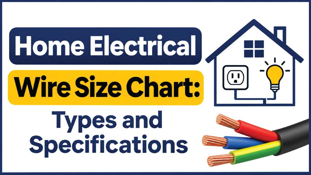
Choosing the correct electrical wire is essential for maintaining a safe, efficient, and reliable home electrical system. Different household circuits require different wire sizes depending on their electrical loads, voltage, current requirements, and installation conditions. Using an incorrectly sized wire can lead to overheating, excessive voltage drop, damaged insulation, and potential electrical fires.
A home electrical wire size chart helps homeowners, electricians, and electrical professionals understand standard conductor sizes, wire types, dimensions, and common residential applications. It also makes it easier to compare American Wire Gauge (AWG) measurements with metric wire sizes used in many countries.
This guide covers common home electrical wire sizes, conductor specifications, insulation types, residential applications, and important factors to consider when selecting electrical wiring.
What Is Home Electrical Wire Size?
Home electrical wire size refers to the thickness or cross-sectional area of a conductor used to carry electricity throughout a residential building. It determines the conductor’s electrical resistance and contributes to its ability to carry current safely.
Electrical wire sizes are generally measured using two systems:
- American Wire Gauge (AWG): A standardized sizing system commonly used in the United States and Canada.
- Metric wire sizing (mm²): A measurement system based on the conductor’s cross-sectional area, commonly used in Europe, Asia, and other regions.
The AWG system works differently from metric sizing. A smaller AWG number indicates a thicker conductor, while a larger metric measurement indicates a greater cross-sectional area.
For example, 10 AWG wire is thicker than 14 AWG wire. Similarly, a 6 mm² conductor has a larger cross-sectional area than a 2.5 mm² conductor.
Wire size is important because electrical conductors must be capable of carrying the required current without exceeding their permitted operating temperature.
Home Electrical Wire Size Chart
The following chart provides common AWG wire sizes, approximate conductor diameters, cross-sectional areas, and typical electrical applications.
Measurements represent the bare conductor and exclude insulation.
| AWG Size | Diameter (mm) | Area (mm²) | Typical Application |
|---|---|---|---|
| 18 AWG | 1.02 | 0.82 | Low-voltage controls |
| 16 AWG | 1.29 | 1.31 | Low-voltage wiring |
| 14 AWG | 1.63 | 2.08 | Certain lighting circuits |
| 12 AWG | 2.05 | 3.31 | Certain outlet circuits |
| 10 AWG | 2.59 | 5.26 | Dedicated appliance circuits |
| 8 AWG | 3.26 | 8.37 | Larger electrical loads |
| 6 AWG | 4.12 | 13.30 | Equipment and feeders |
| 4 AWG | 5.19 | 21.15 | Electrical distribution |
| 3 AWG | 5.83 | 26.67 | Larger feeders |
| 2 AWG | 6.54 | 33.62 | Heavy-duty distribution |
| 1 AWG | 7.35 | 42.41 | Large electrical installations |
| 1/0 AWG | 8.25 | 53.49 | Service conductors |
| 2/0 AWG | 9.27 | 67.43 | Large electrical feeders |
| 3/0 AWG | 10.40 | 85.03 | Heavy electrical distribution |
| 4/0 AWG | 11.68 | 107.22 | Large service applications |
These are standard nominal conductor dimensions. Actual current-carrying capacity, or ampacity, depends on the conductor material, insulation temperature rating, ambient temperature, installation method, and applicable electrical regulations.
Types of Electrical Wires Used in Homes
Residential electrical systems use several types of wires and cables. Each type has different construction characteristics, insulation properties, and intended applications.
Understanding these differences helps determine which wiring products are suitable for particular household installations.
1. Nonmetallic-Sheathed Cable (NM Cable)
Nonmetallic-sheathed cable is commonly used in residential wiring systems in the United States and other locations where local regulations permit it.
It generally contains insulated conductors and a bare or insulated grounding conductor inside a protective nonmetallic outer jacket.
Common characteristics include:
- Lightweight construction.
- Multiple insulated conductors.
- Protective outer sheathing.
- Availability in different conductor sizes.
- Suitability for approved concealed residential installations.
NM cable is commonly identified by designations such as 14/2 and 12/2. The first number indicates the AWG conductor size, while the second indicates the number of insulated circuit conductors. The grounding conductor is generally not included in that count.
2. THHN and THWN Wire
THHN and THWN are common insulation designations for individual electrical conductors.
These wires are frequently installed inside approved conduit systems.
Important characteristics include:
- Thermoplastic insulation.
- Different temperature and moisture ratings depending on the designation.
- Availability in various AWG sizes.
- Suitability for specific conduit and electrical installation applications.
Many modern conductors carry dual THHN/THWN-2 markings, indicating compliance with both applicable designations.
The installation environment and equipment ratings determine which conductor type is appropriate.
3. Armored Cable (AC and MC Cable)
Armored cables have a protective metallic covering around their insulated conductors.
Common types include:
- AC cable.
- MC cable.
Their construction provides additional mechanical protection compared with ordinary nonmetallic-sheathed cable.
Depending on the cable type and local regulations, they may be used in residential walls, ceilings, equipment connections, and other approved installations.
4. Underground Feeder Cable (UF Cable)
Underground feeder cable is designed for applications where moisture resistance and environmental protection are important.
Common characteristics include:
- Moisture-resistant construction.
- Multiple insulated conductors.
- Protective outer jacket.
- Suitability for approved underground installations.
UF cable is commonly used for certain outdoor residential circuits, including approved underground electrical connections.
Its installation depth, protection requirements, and permitted uses depend on local electrical codes.
5. Low-Voltage Electrical Wire
Low-voltage wiring is used for systems that operate at lower voltages than standard household power circuits.
Examples include:
- Doorbells.
- Thermostats.
- Security systems.
- Certain control circuits.
- Communication equipment.
Low-voltage wiring must be selected according to the system’s voltage, current, cable length, and installation requirements.
Home Electrical Wire Size Chart by Amperage
Electrical wire size and circuit amperage must be considered together when designing residential electrical circuits.
The conductor must have sufficient ampacity for the intended load, while the circuit breaker or fuse must provide appropriate overcurrent protection.
The following chart provides common North American copper-wire examples.
| Circuit Rating | Common Copper Wire Size | Typical Application Context |
|---|---|---|
| 15 Amps | 14 AWG | Certain lighting circuits |
| 20 Amps | 12 AWG | Certain receptacle circuits |
| 30 Amps | 10 AWG | Some dedicated appliance circuits |
| 40 Amps | 8 AWG | Selected equipment circuits |
| 50 Amps | 6 AWG | Certain high-demand appliances |
| 60 Amps | 6 AWG or larger | Depends on installation conditions |
Important: These are illustrative pairings, not universal electrical specifications. Actual conductor requirements can differ because of insulation temperature ratings, terminal limitations, conductor material, ambient temperature, cable grouping, and local electrical regulations.
A larger circuit breaker must never be installed without verifying that the conductors and connected equipment are properly rated.
Understanding Electrical Ampacity
Ampacity refers to the maximum current a conductor can safely carry under specified conditions.
Several factors influence a wire’s ampacity:
- Conductor material.
- Cross-sectional area.
- Insulation temperature rating.
- Ambient temperature.
- Number of current-carrying conductors.
- Installation inside conduit or cable assemblies.
- Applicable electrical standards.
A thicker conductor generally has lower electrical resistance than a thinner conductor of the same material and length. However, its permitted ampacity must still be determined using the applicable code requirements.
Metric Home Electrical Wire Size Chart
Many countries use metric measurements for residential electrical conductors. Instead of AWG numbers, metric wire sizes are identified by their cross-sectional area in square millimeters.
Common residential metric sizes include 1.0 mm², 1.5 mm², 2.5 mm², 4 mm², 6 mm², and 10 mm².
The following chart compares these sizes with approximate AWG equivalents.
| Metric Size (mm²) | Approximate AWG Equivalent | Typical Application Context |
|---|---|---|
| 0.75 | 18 AWG | Certain low-load circuits |
| 1.0 | 17 AWG | Small electrical loads |
| 1.5 | 15 AWG | Some lighting circuits |
| 2.5 | 13 AWG | Some socket circuits |
| 4.0 | 11 AWG | Selected higher-load circuits |
| 6.0 | 9 AWG | Larger appliance circuits |
| 10.0 | 7 AWG | Higher-demand installations |
| 16.0 | 5 AWG | Feeders and distribution |
| 25.0 | 3 AWG | Larger electrical distribution |
| 35.0 | 2 AWG | Heavy-duty installations |
These are approximate comparisons based on conductor area, not exact standardized equivalents.
Common Metric Wire Specifications
1.5 mm² Wire
This conductor size is commonly encountered in certain residential lighting installations. Its suitability depends on the protective device and installation conditions.
2.5 mm² Wire
A commonly used size for socket circuits in several metric-based wiring systems. It may also be used for other applications where permitted.
4 mm² Wire
A larger conductor used in selected appliance circuits and installations requiring greater current capacity.
6 mm² Wire
Frequently encountered in certain dedicated appliance circuits and larger residential electrical applications.
10 mm² Wire
Used for selected higher-load circuits, feeders, and electrical distribution applications.
The permitted applications of these metric sizes vary between national wiring standards.
Residential Wire Material Specifications
Electrical conductors are manufactured using different materials. Copper and aluminum are the two main conductor materials found in residential electrical distribution systems.
Copper Electrical Wire
Copper is widely used in household wiring because of its high electrical conductivity and reliable mechanical properties.
Key characteristics include:
- High conductivity.
- Good resistance to corrosion under suitable conditions.
- Availability in solid and stranded forms.
- Compatibility with many residential electrical devices.
- Reliable electrical connections when correctly installed.
Copper is commonly used in residential branch circuits and many appliance connections.
Aluminum Electrical Wire
Aluminum is lighter than copper and is used in certain service and feeder applications.
Its characteristics include:
- Lower weight.
- Different electrical resistance compared with copper.
- Larger conductor dimensions generally required for equivalent electrical performance.
- Specific connector and termination requirements.
Aluminum wiring must be installed with connectors approved for the conductor material and application.
Solid vs. Stranded Wire
Electrical conductors are also classified according to their physical construction.
| Feature | Solid Wire | Stranded Wire |
|---|---|---|
| Construction | One continuous conductor | Multiple smaller strands |
| Flexibility | Lower | Higher |
| Mechanical stability | Good for fixed installations | Suitable for flexible connections |
| Common uses | Fixed residential wiring | Equipment and flexible connections |
| Termination | Compatible solid-wire terminals | Compatible stranded-wire terminals |
Neither construction is universally better. The correct choice depends on the wiring application and the terminals or connectors being used.
Also Read:
Residential Electrical Wire Color Codes
Wire color identification helps distinguish different electrical conductors and their functions. However, color conventions vary between countries and electrical standards.
The following table shows common North American color conventions.
| Wire Color | Common Function | Important Information |
|---|---|---|
| Black | Hot conductor | Carries current from the supply |
| Red | Hot conductor | Often used for additional switched or live conductors |
| White | Neutral conductor | Normally grounded at the system bonding point |
| Gray | Neutral conductor | Used as a neutral identification color |
| Green | Equipment grounding conductor | Provides a protective grounding path |
| Green with yellow stripes | Grounding conductor | Common in IEC-based systems |
Important: Never identify a conductor’s function by color alone. Previous modifications, different national standards, and incorrect installations can result in unexpected wiring colors. Always verify conductors using appropriate electrical testing procedures.
How to Select the Correct Home Electrical Wire Size
Choosing the correct wire requires more than checking an amperage chart. Several electrical and environmental factors influence conductor selection.
1. Calculate the Electrical Load
Begin by identifying the power requirements of the connected equipment.
For a basic single-phase circuit, the current can be estimated using:
[
I=\frac{P}{V}
]
Where:
- I = Current in amperes.
- P = Power in watts.
- V = Supply voltage in volts.
For example, an appliance rated at 2,000 watts operating at 230 volts draws approximately:
[
I=\frac{2000}{230}=8.7A
]
This calculation provides an approximate operating current. Final circuit design must also consider continuous loads, motor starting current, power factor where relevant, and local code requirements.
2. Consider Wire Length
Longer electrical runs generally experience greater voltage drop.
A larger conductor may be required to maintain acceptable voltage at the connected equipment.
3. Identify the Conductor Material
Copper and aluminum have different electrical characteristics.
The selected wire size must account for conductor material, ampacity, and approved connection methods.
4. Check Circuit Protection
The circuit breaker or fuse must be properly coordinated with the conductor and equipment.
Never install a higher-rated breaker simply to prevent frequent tripping.
5. Evaluate Installation Conditions
Wire ampacity can be affected by:
- High ambient temperatures.
- Multiple conductors grouped together.
- Conduit installation.
- Cable insulation ratings.
- Exposure to moisture.
- Restricted heat dissipation.
6. Follow Local Electrical Codes
Residential electrical requirements differ between countries.
The NEC is commonly used in the United States, while many other countries use IEC-based or national wiring regulations.
Always follow the electrical standards applicable to the installation.
Also Read:
Understanding Voltage Drop in Home Electrical Wiring
Voltage drop is the reduction in electrical voltage that occurs as current travels through a conductor.
Electrical wires have resistance, so some energy is converted into heat when current flows through them.
Voltage drop becomes more significant when:
- The cable is long.
- The connected equipment draws high current.
- The conductor is undersized.
- The conductor material has higher resistance.
- The circuit carries heavy electrical loads.
Ways to Reduce Voltage Drop
The following measures can help maintain acceptable voltage:
- Use an appropriately sized conductor.
- Avoid unnecessarily long cable routes.
- Calculate the expected electrical load.
- Select suitable conductor materials.
- Follow the recommended voltage-drop limits in the applicable electrical standard.
Increasing conductor cross-sectional area generally reduces resistance and helps limit voltage drop.
Also Read:
Common Applications of Home Electrical Wires
Residential electrical systems contain several types of circuits, each designed for particular electrical loads.
| Application | Common Wiring Context | Main Selection Factor |
|---|---|---|
| Lighting | 14 AWG or 1.5 mm² in some systems | Circuit rating |
| General outlets | 12 AWG or 2.5 mm² in some systems | Connected load |
| Kitchen appliances | Dedicated or specially protected circuits | Appliance requirements |
| Washing machines | Designated or dedicated circuits | Rated electrical demand |
| Water heaters | Dedicated circuits | Manufacturer specifications |
| Air conditioners | Dedicated circuits | Minimum circuit ampacity |
| Electric dryers | Dedicated circuits | Voltage and rated current |
| Electric ranges | Dedicated circuits | Equipment load |
| Subpanels | Larger feeder conductors | Calculated feeder load |
| Main electrical service | Service-rated conductors | Total electrical demand |
These are general examples rather than universal wire-size recommendations. Always verify the actual conductor requirements before installation.
Common Home Electrical Wiring Mistakes
Incorrect wire selection or installation can create safety hazards and affect the performance of electrical equipment.
Using Undersized Wire
An undersized conductor may overheat when carrying excessive current. This can damage insulation and increase the risk of electrical fires.
Using an Incorrect Circuit Breaker
The protective device must be compatible with the conductor’s ampacity and circuit design. An oversized breaker can leave wiring inadequately protected.
Ignoring Cable Length
Longer cable runs may require larger conductors to control voltage drop.
Mixing Copper and Aluminum Without Approved Connectors
Different conductor materials require compatible connectors and approved termination procedures.
Using Indoor Cable Outdoors
Not all residential cables are suitable for wet locations, underground installations, or outdoor exposure.
Ignoring Grounding Requirements
Proper grounding and bonding are essential for electrical safety. The required protective conductors must be installed according to the applicable electrical standards.
Frequently Asked Questions About Home Electrical Wire Sizes
What Is the Most Common Wire Size Used in Homes?
In North American residential wiring, 14 AWG and 12 AWG copper conductors are commonly used for certain 15-amp and 20-amp branch circuits.
In metric-based systems, 1.5 mm² and 2.5 mm² conductors are frequently encountered in lighting and socket installations.
What Is the Difference Between 12 AWG and 14 AWG Wire?
12 AWG is thicker than 14 AWG. Its approximate conductor diameter is 2.05 mm, compared with 1.63 mm for 14 AWG.
Which Wire Is Used for a 20-Amp Circuit?
12 AWG copper is commonly used for certain 20-amp branch circuits in North America. The final selection must comply with the applicable electrical code and installation requirements.
What Is the Difference Between 1.5 mm² and 2.5 mm² Wire?
The 2.5 mm² conductor has a larger cross-sectional area than the 1.5 mm² conductor. It generally has lower resistance for the same material and length, but its permitted current capacity still depends on installation conditions.
Is Copper Wire Better Than Aluminum Wire?
Copper offers higher electrical conductivity for the same conductor dimensions and is commonly used in household branch circuits. Aluminum is lighter and is suitable for certain larger feeders when correctly sized and connected.
Does Wire Size Affect Electrical Efficiency?
Yes. A conductor with lower resistance generally produces less voltage drop and resistive power loss for the same current and length.
Can I Use the Same Wire Size for Every Room?
No. Different circuits may supply different electrical loads and require different conductor sizes. Lighting, general outlets, kitchen equipment, and large appliances must be designed according to their electrical requirements.
How Do I Know If My Home Electrical Wire Is Undersized?
Wire sizing cannot be reliably determined from appearance alone. A qualified electrician can inspect the conductor markings, calculate the circuit load, verify the protective device, and evaluate installation conditions.
Conclusion
Selecting the correct electrical wire is essential for maintaining a safe and reliable home electrical system. Common residential conductor sizes include 14 AWG, 12 AWG, 10 AWG, and larger AWG conductors, while metric systems commonly use 1.5 mm², 2.5 mm², 4 mm², and 6 mm² wires.
Understanding wire types, conductor materials, insulation specifications, color identification, and current-carrying capacity makes residential wiring easier to evaluate.
Use the home electrical wire size chart as a reference for standard measurements and common applications. Always verify conductor ampacity, voltage drop, circuit protection, and local electrical requirements before selecting or installing electrical wiring.