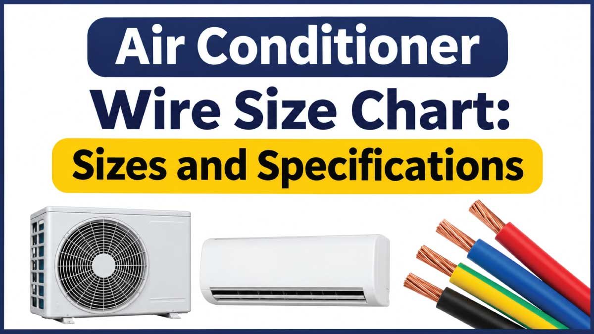
Choosing the correct electrical wire for an air conditioner is essential for safe operation, reliable performance, and preventing overheating. An undersized wire can overheat, damage insulation, trip circuit breakers, and create a fire hazard. An oversized wire may also increase installation costs without providing any practical benefit.
An air conditioner wire size chart helps homeowners, electricians, and HVAC technicians understand common wire gauges, conductor ampacity, and electrical requirements for different air conditioning systems. However, the correct wire size depends on more than the cooling capacity of the unit.
This guide explains air conditioner wire sizes, American Wire Gauge (AWG), copper and aluminum conductors, minimum circuit ampacity (MCA), maximum overcurrent protection (MOCP), breaker requirements, and practical selection considerations.
Air Conditioner Wire Size Chart
Air conditioner wiring requirements vary according to the equipment’s voltage, electrical load, compressor characteristics, installation conditions, and manufacturer specifications.
The following table provides a general reference for common copper conductor sizes. These are illustrative ampacity values based on commonly used North American conductor ratings, not universal air conditioner circuit ratings.
General Copper Wire Ampacity Chart
| Wire Size (AWG) | Ampacity at 60°C | Ampacity at 75°C | Common Applications |
|---|---|---|---|
| 14 AWG | 15 A | 20 A | Small electrical circuits |
| 12 AWG | 20 A | 25 A | General-purpose circuits |
| 10 AWG | 30 A | 35 A | Medium electrical loads |
| 8 AWG | 40 A | 50 A | Higher-current circuits |
| 6 AWG | 55 A | 65 A | Large electrical loads |
| 4 AWG | 70 A | 85 A | Heavy electrical circuits |
| 3 AWG | 85 A | 100 A | Higher-capacity installations |
| 2 AWG | 95 A | 115 A | Large electrical equipment |
| 1 AWG | 110 A | 130 A | High-current applications |
| 1/0 AWG | 125 A | 150 A | Heavy-duty installations |
Important: Values are general reference ampacities for copper conductors under specified temperature-column conditions. Actual allowable ampacity depends on conductor insulation, terminal temperature ratings, installation conditions, ambient temperature, conductor grouping, and applicable electrical codes. These figures must not be used alone to select an air conditioner circuit.
How to Read the Wire Size Chart
Air conditioner wire sizes are generally expressed using the American Wire Gauge system.
-
AWG: A standard system used to identify electrical conductor sizes.
-
Ampacity: The maximum current a conductor can carry under specified conditions.
-
60°C and 75°C ratings: Temperature columns used when determining allowable conductor ampacity.
-
Copper wire: A commonly used conductor because of its electrical conductivity.
-
Aluminum wire: A lighter alternative that requires appropriate sizing and compatible electrical connections.
One important detail is that smaller AWG numbers represent thicker wires. For example, 8 AWG wire is thicker than 12 AWG wire.
The chart provides a starting point for understanding conductor sizes, but the air conditioner’s nameplate and installation instructions must determine the final selection.
Understanding Air Conditioner Electrical Requirements
Before choosing an electrical cable, it is important to understand the basic specifications printed on an air conditioner’s rating plate.
These specifications describe how much electrical power the equipment requires and what protection its circuit needs.
Voltage Requirements
Voltage is the electrical potential supplied to the air conditioner. Residential air conditioning equipment commonly operates on different supply voltages depending on its capacity and design.
| Air Conditioner Type | Common Supply Voltage | Typical Application |
|---|---|---|
| Small window AC | 115–120 V | Small rooms |
| Larger window AC | 208–240 V | Medium-sized rooms |
| Mini-split AC | 208–240 V | Residential cooling |
| Central air conditioner | 208–240 V | Whole-house cooling |
| Commercial HVAC equipment | Varies | Commercial buildings |
These are common supply-voltage categories, not universal specifications. Always check the equipment nameplate before connecting an air conditioner.
Minimum Circuit Ampacity (MCA)
Minimum Circuit Ampacity, commonly abbreviated as MCA, identifies the minimum ampacity required for the branch-circuit conductors supplying the equipment.
It is particularly important for air conditioning systems because compressors and other motor loads can have different electrical characteristics.
For example, if an air conditioner nameplate specifies an MCA of 24 amperes, the selected conductors must have an allowable ampacity of at least 24 amperes after applicable adjustments and corrections.
The final conductor size must also comply with local electrical requirements.
Maximum Overcurrent Protection (MOCP)
Maximum Overcurrent Protection, or MOCP, identifies the maximum permitted rating of the circuit breaker or fuse protecting the equipment.
For example, if the equipment nameplate specifies a maximum overcurrent protection of 35 amperes, the installed breaker or fuse must not exceed that rating.
MCA and MOCP serve different purposes:
-
MCA helps determine the minimum conductor ampacity.
-
MOCP establishes the maximum permitted overcurrent protection.
-
The breaker or fuse protects the circuit against specified overcurrent conditions.
-
The conductor must meet the equipment and applicable code requirements.
Never assume that the breaker rating and wire ampacity must always have identical numerical values. Air conditioning equipment has specific motor-circuit rules.
Air Conditioner Wire Size by BTU Capacity
Air conditioner capacity is commonly measured in British Thermal Units per hour (BTU/h). Higher BTU ratings generally indicate greater cooling capacity, but they do not directly determine the required electrical wire size.
Two air conditioners with identical cooling capacities may have different electrical requirements because of differences in compressor efficiency, voltage, design, and operating current.
The following chart provides general equipment categories rather than guaranteed wire-size recommendations.
| AC Capacity (BTU/h) | Cooling Category | Common Equipment Type | Wire Selection Basis |
|---|---|---|---|
| 5,000–6,000 | Small | Window AC | Nameplate MCA |
| 8,000–10,000 | Small to medium | Window AC | Nameplate MCA |
| 12,000 | Medium | Window or mini-split | Nameplate MCA |
| 18,000 | Medium to large | Mini-split | Nameplate MCA |
| 24,000 | Large | Mini-split | Nameplate MCA |
| 30,000–36,000 | Large | Split or central AC | Nameplate MCA |
| 48,000–60,000 | Extra large | Central AC | Nameplate MCA |
Why BTU Capacity Is Not Enough
BTU capacity measures cooling output, not electrical current.
The actual electrical demand depends on several characteristics:
-
Compressor rated-load current.
-
Operating voltage.
-
Motor efficiency.
-
Electrical input power.
-
Starting characteristics.
-
Additional components such as fans and heating elements.
For this reason, selecting a wire solely from the BTU rating can result in an undersized or unnecessarily oversized conductor.
Best practice: Use BTU capacity to understand the cooling category, then use the manufacturer’s electrical specifications to determine the correct conductor size.
Air Conditioner Wire Size by Amperage
Amperage is one of the most important considerations when selecting an electrical conductor for an air conditioning system.
A higher electrical current generally requires a conductor with greater allowable ampacity, subject to installation and code requirements.
The following chart illustrates commonly encountered copper conductor ampacity values.
| Copper Wire Size (AWG) | 60°C Ampacity | 75°C Ampacity |
|---|---|---|
| 14 AWG | 15 A | 20 A |
| 12 AWG | 20 A | 25 A |
| 10 AWG | 30 A | 35 A |
| 8 AWG | 40 A | 50 A |
| 6 AWG | 55 A | 65 A |
| 4 AWG | 70 A | 85 A |
| 3 AWG | 85 A | 100 A |
| 2 AWG | 95 A | 115 A |
| 1 AWG | 110 A | 130 A |
These values refer to common copper conductor ampacity references, not automatically permitted breaker sizes.
Selecting Wire According to Current
Consider the following general process:
-
Locate the air conditioner’s nameplate.
-
Find the minimum circuit ampacity.
-
Identify the conductor material and insulation type.
-
Check the applicable temperature rating of the terminals.
-
Account for ambient temperature and conductor grouping.
-
Check voltage drop for the circuit length.
-
Verify that the selected conductor satisfies local electrical codes.
For instance, if an air conditioner requires an MCA of 28 amperes, the selected conductor must provide at least 28 amperes of allowable ampacity after all applicable adjustments.
A 10 AWG copper conductor may be suitable in certain installations, but its actual allowable ampacity must be verified. It should not be selected simply because a general chart lists a particular current rating.
Copper vs. Aluminum Wire for Air Conditioners
Copper and aluminum are both used in electrical installations, but they have different physical and electrical characteristics.
Choosing between them requires considering conductor size, connection compatibility, installation conditions, and manufacturer requirements.
Copper Wire
Copper is commonly used for residential air conditioner branch circuits.
Its main advantages include:
-
High electrical conductivity.
-
Smaller conductor size for comparable electrical performance.
-
Good mechanical strength.
-
Wide availability.
-
Compatibility with many standard electrical terminals.
Copper is often preferred for smaller residential HVAC circuits because of its conductivity and installation convenience.
Aluminum Wire
Aluminum is another conductor option, particularly for larger electrical circuits.
Its characteristics include:
-
Lower weight than copper.
-
Generally lower material cost.
-
Larger conductor size required for comparable ampacity.
-
Greater attention required for connection preparation and termination.
-
Need for terminals specifically identified for aluminum conductors.
Aluminum conductors must be installed using appropriately listed equipment and approved connection methods.
Copper and Aluminum Comparison
| Characteristic | Copper Wire | Aluminum Wire |
|---|---|---|
| Electrical conductivity | Higher | Lower |
| Weight | Heavier | Lighter |
| Conductor size | Generally smaller | Generally larger |
| Material cost | Generally higher | Generally lower |
| Connection requirements | Standard compatible terminals | Aluminum-rated terminals |
| Corrosion considerations | Generally lower | Requires proper connection practices |
| Common use | Residential branch circuits | Larger electrical feeders and circuits |
For most air conditioner installations, the equipment manufacturer determines which conductor materials are acceptable.
Air Conditioner Wire Types and Specifications
Selecting the correct wire gauge is only one part of an electrical installation. The insulation type, conductor construction, and cable rating are also important.
Different wiring products are designed for different installation environments.
THHN and THWN-2 Wire
THHN and THWN-2 are common building-wire designations.
-
THHN: Thermoplastic, heat-resistant, nylon-coated wire intended for permitted dry-location applications.
-
THWN-2: Thermoplastic, heat- and moisture-resistant wire rated for wet and dry locations.
Many modern building wires carry both THHN and THWN-2 markings.
These conductors are commonly installed inside an approved electrical raceway. They are not automatically suitable for direct burial or exposed outdoor installation.
NM-B Cable
Nonmetallic-sheathed cable, commonly called NM-B, is used in permitted residential building installations.
It contains insulated conductors within an outer nonmetallic jacket.
However, NM-B is generally restricted to permitted dry locations and must not be used in locations where the wiring method is prohibited by electrical code.
UF-B Cable
Underground Feeder cable, or UF-B, is designed for applications permitted by its listing, including certain underground installations.
Its suitability depends on the installation environment, equipment instructions, and applicable electrical requirements.
Flexible HVAC Whip
An electrical whip is a short flexible wiring assembly used to connect an outdoor air conditioning unit to a nearby disconnect.
It typically provides protection for the final connection between the building wiring and the equipment.
The whip must have suitable conductor sizes, fittings, environmental ratings, and electrical ratings for the installation.
Air Conditioner Breaker and Wire Size Chart
An air conditioner circuit breaker protects the electrical circuit against overcurrent conditions.
However, selecting a breaker is not as simple as matching it to a wire gauge. Air conditioning equipment often uses specific motor-circuit protection requirements.
The equipment nameplate normally provides the maximum fuse or circuit breaker rating.
| Electrical Specification | Meaning | Purpose |
|---|---|---|
| MCA | Minimum Circuit Ampacity | Determines minimum conductor ampacity |
| MOCP | Maximum Overcurrent Protection | Establishes maximum permitted fuse or breaker rating |
| Voltage | Rated supply voltage | Identifies the required electrical supply |
| RLA | Rated Load Amps | Indicates compressor operating-current information |
| LRA | Locked Rotor Amps | Indicates compressor starting-current characteristics |
How to Choose the Correct Breaker
Follow these general steps:
-
Read the air conditioner nameplate.
-
Identify its maximum overcurrent protection rating.
-
Determine whether the manufacturer permits a circuit breaker, fuse, or both.
-
Select a suitable protective device within the specified limit.
-
Verify the conductor sizing and circuit installation requirements.
For example, if the nameplate lists a maximum breaker rating of 40 amperes, a 45-ampere breaker would exceed the equipment’s specified maximum.
The installed breaker must also comply with applicable electrical codes and the equipment’s instructions.
Also Read:
How to Determine the Correct Air Conditioner Wire Size
Selecting an appropriate conductor involves evaluating the equipment requirements and the conditions under which the circuit will operate.
The following process helps explain how electricians approach air conditioner wire sizing.
Step 1: Check the Equipment Nameplate
Locate the electrical rating label on the outdoor condenser, indoor equipment, or manufacturer’s documentation.
Look for:
-
Rated voltage.
-
Minimum circuit ampacity.
-
Maximum overcurrent protection.
-
Electrical input specifications.
-
Approved wiring requirements.
The MCA and MOCP are particularly important for determining conductor and protective-device requirements.
Step 2: Identify the Conductor Material
Determine whether the installation uses copper or aluminum.
The selected conductor must have adequate allowable ampacity for its material and size.
Do not use copper ampacity values when sizing aluminum conductors.
Step 3: Consider Wire Length
Long electrical runs can experience voltage drop.
Voltage drop occurs when electrical resistance in the conductors reduces the voltage available at the equipment.
It can be affected by:
-
Circuit length.
-
Electrical current.
-
Conductor material.
-
Conductor cross-sectional area.
-
Operating voltage.
Longer circuits may require larger conductors to maintain acceptable voltage at the equipment.
Step 4: Check Installation Conditions
The same conductor may have different allowable ampacity depending on how it is installed.
Important considerations include:
-
Ambient temperature.
-
Number of current-carrying conductors.
-
Raceway conditions.
-
Insulation temperature rating.
-
Terminal temperature limitations.
-
Local electrical regulations.
Step 5: Verify the Final Selection
Before installation, compare the selected conductor with the air conditioner’s documentation and applicable electrical requirements.
Also confirm that the disconnect, circuit breaker, terminals, and wiring method are appropriately rated.
Also Read:
Wire Size for Different Air Conditioner Types
Different air conditioning systems have different electrical configurations. Their wiring requirements should be evaluated according to their individual designs.
Window Air Conditioner Wire Size
Window air conditioners are generally smaller self-contained systems.
Some models operate on 115–120 V supplies, while larger units may require 208–240 V.
The correct branch-circuit conductor depends on the equipment’s rated current, MCA where provided, plug configuration, and manufacturer instructions.
Avoid using extension cords or adapters unless the manufacturer specifically permits them.
Mini-Split Air Conditioner Wire Size
Mini-split systems commonly use dedicated electrical circuits.
Their electrical arrangements can vary depending on whether the supply connects to the outdoor condenser or indoor unit.
Important considerations include:
-
Manufacturer-specified voltage.
-
MCA and MOCP.
-
Interconnecting cable specifications.
-
Outdoor installation conditions.
-
Communication-wire requirements.
The power conductors and communication conductors serve different purposes and must not be confused.
Central Air Conditioner Wire Size
Central air conditioning systems generally have larger electrical requirements than small window units.
They commonly use dedicated branch circuits and outdoor disconnects.
The conductor size depends on the condenser’s nameplate specifications, circuit length, installation method, and applicable electrical requirements.
Portable Air Conditioner Wire Size
Portable air conditioners are commonly designed to operate using a suitable household receptacle.
Their electrical requirements vary by model and voltage rating.
Always follow the manufacturer’s instructions regarding outlet ratings, circuit requirements, and extension-cord restrictions.
Also Read:
Common Air Conditioner Wiring Mistakes to Avoid
Incorrect wiring practices can reduce equipment reliability and create serious electrical hazards.
Some common mistakes include:
-
Choosing wire by BTU alone: Cooling capacity does not directly establish the required conductor ampacity.
-
Ignoring MCA: The minimum circuit ampacity is an important equipment specification.
-
Exceeding MOCP: Installing a breaker or fuse above the permitted rating can compromise equipment protection.
-
Using undersized conductors: Insufficient conductor ampacity can cause excessive heating.
-
Ignoring voltage drop: Long circuits may require additional conductor sizing.
-
Using incompatible terminals: Aluminum and copper conductors require appropriately rated connections.
-
Ignoring outdoor conditions: Outdoor wiring needs suitable environmental protection.
-
Using an incorrect disconnect: Disconnecting equipment must meet the applicable electrical ratings and installation requirements.
Never replace a frequently tripping breaker with a larger one without identifying the underlying problem.
Safety Considerations for Air Conditioner Electrical Installation
Air conditioning systems combine high electrical currents, motor loads, and outdoor equipment. Incorrect installation can cause electric shock, overheating, equipment damage, or fire.
Keep these precautions in mind:
-
Turn off and verify the electrical supply before servicing equipment.
-
Follow the manufacturer’s installation instructions.
-
Use appropriately rated conductors and electrical components.
-
Provide required grounding and bonding.
-
Install suitable disconnecting equipment where required.
-
Protect outdoor wiring against environmental damage.
-
Use properly rated electrical enclosures and fittings.
-
Follow local electrical codes and inspection requirements.
Electrical installation and circuit modifications should be performed by a qualified electrician or appropriately licensed professional.
A circuit breaker being switched off does not necessarily prove that every conductor is de-energized. Proper testing and safe isolation procedures are essential.
Frequently Asked Questions About Air Conditioner Wire Sizes
What Size Wire Is Needed for an Air Conditioner?
The required wire size depends on the equipment’s minimum circuit ampacity, conductor material, installation conditions, circuit length, and applicable electrical code.
There is no single wire gauge suitable for every air conditioner.
Is 12 AWG Wire Suitable for an Air Conditioner?
12 AWG copper wire may be suitable for certain smaller air conditioning circuits, depending on the equipment specifications and installation conditions.
However, it is not appropriate for every air conditioner. Always verify the required MCA and applicable conductor ampacity.
Can I Use 10 AWG Wire for a 240V Air Conditioner?
10 AWG copper wire may be appropriate for certain 240 V air conditioning installations.
However, voltage alone does not determine wire size. The equipment’s electrical requirements and circuit conditions must be checked first.
Does a Larger Air Conditioner Always Need Thicker Wire?
Not necessarily. Larger cooling capacity often corresponds to higher electrical demand, but efficiency, compressor design, voltage, and other equipment characteristics also influence current requirements.
The nameplate provides more useful information for wire selection than BTU capacity alone.
What Is the Difference Between MCA and MOCP?
MCA specifies the minimum required conductor ampacity, while MOCP specifies the maximum permitted overcurrent protection rating.
Both values are important when designing an air conditioner branch circuit.
Should Air Conditioner Wiring Be Copper or Aluminum?
Both materials can be used in suitable installations. Copper is commonly selected for smaller residential branch circuits, while aluminum is also used in larger electrical applications.
The equipment terminals, conductor ratings, and applicable electrical code determine acceptable materials.
Does a Long Wire Run Require a Larger Wire Size?
A long circuit can experience greater voltage drop because of conductor resistance.
Depending on the circuit length and electrical load, a larger conductor may be necessary to maintain acceptable voltage at the air conditioner.
Can an Air Conditioner Share a Circuit With Other Appliances?
This depends on the equipment listing, manufacturer instructions, circuit design, and applicable electrical code.
Many air conditioning systems require individual branch circuits. Never assume that a shared circuit is acceptable without verifying the requirements.
Conclusion
Selecting the correct conductor is essential for safe and reliable air conditioner operation. An air conditioner wire size chart provides a useful reference for understanding AWG measurements, copper wire ampacity, and common electrical specifications.
However, BTU capacity and voltage alone cannot determine the correct wire size. Always check the equipment’s minimum circuit ampacity (MCA), maximum overcurrent protection (MOCP), conductor material, circuit length, installation conditions, and local electrical requirements.
Using the manufacturer’s specifications and following approved electrical installation practices helps ensure that an air conditioning system operates safely and reliably.