
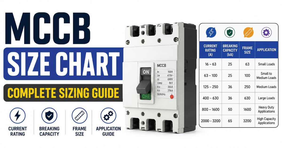
An MCCB size chart helps electricians, engineers, contractors, and facility managers understand molded case circuit breaker ratings and their relationship with electrical loads, cable capacity, voltage, and fault protection. Proper MCCB selection is essential for larger electrical systems.
MCCBs are commonly used in commercial, industrial, and large residential installations where higher current ratings and adjustable protection may be required. Understanding amp ratings, breaking capacity, poles, trip characteristics, and applications makes MCCB selection easier.
What Is an MCCB?
A Molded Case Circuit Breaker (MCCB) is an electrical protection device designed to protect circuits from overloads and short circuits. MCCBs are generally used for higher-current applications than miniature circuit breakers and can provide additional protection and adjustment features.
MCCBs are commonly used in:
- Industrial distribution systems
- Commercial buildings
- Large feeders
- Motor circuits
- Transformers
- Generators
- Subpanels
- Manufacturing equipment
- Large electrical installations
How Does an MCCB Work?
An MCCB monitors current flowing through an electrical circuit and interrupts the circuit when an excessive current or fault occurs. Depending on the MCCB design, its protection settings may be fixed or adjustable.
An MCCB can provide protection against:
- Overloads
- Short circuits
- Excessive current
- Certain ground-fault conditions
- Equipment faults
The breaker interrupts the circuit to help prevent excessive conductor heating and equipment damage.
MCCB Size and Ampere Rating
MCCB size is commonly identified by its ampere rating or frame size. Unlike simple branch-circuit breakers, MCCBs are available in much larger current ratings for feeders, distribution systems, motors, and industrial equipment.
Common MCCB ratings include:
- 15A
- 20A
- 30A
- 40A
- 50A
- 60A
- 100A
- 125A
- 160A
- 200A
- 250A
- 400A
- 600A
- 800A
- 1000A
- 1200A
- 1600A
- 2000A
- 2500A
- 3200A
The available ratings vary by manufacturer, series, frame size, voltage, and application.
MCCB Size Chart
MCCBs are manufactured in a wide range of current ratings. The following chart provides a general reference for common MCCB sizes and typical applications.
| MCCB Rating | Typical Application | Common System |
|---|---|---|
| 60A | Small equipment/feeders | Commercial |
| 100A | Feeders/subpanels | Residential/Commercial |
| 125A | Distribution circuits | Commercial |
| 160A | Equipment/feeders | Commercial |
| 200A | Large feeders | Commercial/Industrial |
| 250A | Distribution systems | Industrial |
| 400A | Large feeders | Industrial |
| 600A | Main distribution | Industrial |
| 800A | Large distribution | Industrial |
| 1000A | Major feeders | Industrial |
| 1200A | Large distribution | Industrial |
| 1600A | Main feeders | Industrial |
| 2000A | High-current systems | Industrial |
| 2500A | Large distribution | Industrial |
| 3200A | Major electrical systems | Industrial |
These are general reference ratings. Actual MCCB availability and selection depend on manufacturer specifications, load calculations, voltage, fault current, conductor ampacity, and applicable electrical standards.
Also Read: Electrical Wire Size Chart: Choose the Right Wire Gauge
MCCB Frame Size vs Trip Rating
Frame size and trip rating are not always the same thing. The frame identifies the physical and current-capacity family of an MCCB, while the trip unit determines the protection settings available within that frame.
For example, an MCCB may have:
- A particular frame size
- A lower rated trip unit
- Adjustable long-time protection
- Adjustable short-time protection
- Instantaneous protection
- Ground-fault protection
This flexibility makes MCCBs useful for larger electrical distribution systems.
What Is MCCB Frame Size?
The MCCB frame size represents the physical size and maximum current capability of a particular breaker family. Multiple trip ratings may sometimes be available within the same frame size.
Frame size affects:
- Maximum current rating
- Physical dimensions
- Terminal arrangement
- Available trip units
- Interrupting capacity
- Mounting requirements
- Accessories
Always check the manufacturer’s technical documentation when selecting a specific MCCB frame.
What Determines MCCB Size?
MCCB selection depends on the electrical load and the complete design of the circuit. A breaker should not be selected simply because its amp rating is close to the expected operating current.
Important factors include:
- Connected load
- Conductor ampacity
- System voltage
- Phase configuration
- Continuous load
- Short-circuit current
- Motor starting current
- Trip-unit settings
- Breaking capacity
- Ambient temperature
- Installation conditions
A proper electrical load calculation should be completed before selecting the MCCB.
MCCB Size and Cable Size
The MCCB and cable must be properly coordinated so that the protective device provides appropriate overcurrent protection for the conductors. Larger cables generally support higher current, but actual ampacity depends on installation conditions.
| Cable Size | General MCCB Reference* |
|---|---|
| 16 mm² | Up to around 63A |
| 25 mm² | Around 63–100A |
| 35 mm² | Around 80–125A |
| 50 mm² | Around 100–160A |
| 70 mm² | Around 125–200A |
| 95 mm² | Around 160–250A |
| 120 mm² | Around 200–315A |
| 150 mm² | Around 250–400A |
| 185 mm² | Around 315–500A |
| 240 mm² | Around 400–630A |
These are broad reference ranges only. Actual cable ampacity depends on conductor material, insulation, installation method, ambient temperature, grouping, voltage drop, and applicable standards.
Also Read: Welding Cable Size Chart: Choose the Right Cable Size
MCCB Breaking Capacity
Breaking capacity indicates the maximum fault current an MCCB is designed to interrupt safely under specified conditions. This is one of the most important specifications when selecting an MCCB for a high-current electrical system.
Common interrupting-capacity ratings may include:
- 18 kA
- 25 kA
- 36 kA
- 50 kA
- 65 kA
- 85 kA
- 100 kA
The required rating depends on the prospective short-circuit current at the installation location.
MCCB Voltage Rating
Every MCCB has a maximum system voltage for which it is designed and tested. The breaker must be suitable for the electrical system where it will be installed.
Common system voltages include:
- 120V
- 208V
- 220V
- 230V
- 240V
- 380V
- 400V
- 415V
- 480V
- 600V
Voltage rating should always be verified from the MCCB manufacturer’s specifications before installation.
MCCB Poles
MCCBs are available with different numbers of poles depending on the electrical system and circuit configuration. Pole selection determines which conductors are switched or protected by the device.
Common configurations include:
| MCCB Poles | Typical Application |
|---|---|
| 2-Pole | Single-phase/two-conductor systems |
| 3-Pole | Three-phase systems |
| 4-Pole | Three-phase systems with neutral switching |
The appropriate pole configuration depends on the system design and applicable electrical requirements.
Also Read: Solar Cable Size Chart: Choose the Right Cable Size
3 Pole MCCB
A 3-pole MCCB is commonly used in three-phase electrical systems. It provides protection across three phases and is widely used for industrial equipment, motors, feeders, and commercial distribution systems.
Typical applications include:
- Three-phase motors
- Pumps
- Compressors
- Industrial machinery
- Distribution feeders
- Commercial equipment
- Transformers
The MCCB rating should be coordinated with the three-phase load and conductor capacity.
4 Pole MCCB
A 4-pole MCCB can provide switching and protection arrangements for three-phase systems that include a neutral. The exact neutral-pole function depends on the MCCB design and system requirements.
Potential applications include:
- Commercial distribution boards
- Industrial systems
- Generator systems
- Transfer arrangements
- Large three-phase installations
Always verify whether the neutral pole is required to be switched or protected according to the system design.
MCCB Trip Unit Types
The trip unit controls how an MCCB responds to abnormal current conditions. Depending on the model, MCCBs may use thermal-magnetic or electronic trip units with fixed or adjustable settings.
Common protection functions include:
- Long-time overload protection
- Short-time protection
- Instantaneous protection
- Ground-fault protection
Electronic trip units can provide greater adjustment and monitoring capabilities for complex distribution systems.
Thermal Magnetic MCCB
A thermal-magnetic MCCB generally combines thermal protection for overload conditions with magnetic protection for short-circuit conditions. This type is widely used in many commercial and industrial electrical applications.
Thermal-magnetic MCCBs can be suitable for:
- Feeders
- Distribution panels
- Motors
- Commercial equipment
- Industrial machinery
- General electrical systems
The exact operating characteristics depend on the MCCB design and manufacturer.
Electronic MCCB
Electronic MCCBs use electronic trip units to monitor current and control protective functions. They can provide more precise adjustment options than many traditional thermal-magnetic designs.
Features may include:
- Adjustable long-time pickup
- Adjustable short-time pickup
- Instantaneous protection
- Ground-fault protection
- Current monitoring
- Trip indication
- Communication features on selected models
Electronic MCCBs are particularly useful in larger electrical distribution systems where coordination and protection settings are important.
Adjustable MCCB
An adjustable MCCB allows selected protection parameters to be configured within the limits of the trip unit. This provides greater flexibility when coordinating multiple protective devices.
Adjustable settings may include:
- Long-time pickup
- Short-time pickup
- Instantaneous pickup
- Ground-fault pickup
- Time delays
Adjustment should be performed according to the system protection study, equipment requirements, and manufacturer’s instructions.
Fixed MCCB
A fixed MCCB has predetermined protection characteristics that generally cannot be adjusted by the user in the same way as an electronic adjustable trip unit.
Fixed MCCBs can be useful for:
- Smaller distribution systems
- Straightforward feeder protection
- Standard equipment circuits
- Applications with predictable loads
- Systems where adjustable protection is unnecessary
The fixed rating must still be correctly coordinated with the conductors and load.
MCCB vs MCB
MCBs and MCCBs both provide overcurrent protection, but they are designed for different ranges of applications. MCCBs are generally used for larger current ratings and more demanding electrical distribution systems.
| Feature | MCB | MCCB |
|---|---|---|
| Typical Current | Lower | Higher |
| Physical Size | Smaller | Larger |
| Trip Adjustment | Limited | Often available |
| Breaking Capacity | Generally lower | Often higher |
| Applications | Branch circuits | Feeders/distribution |
| Electronic Trip | Less common | Common on larger models |
| Industrial Use | Limited | Extensive |
The appropriate device depends on the electrical system and protection requirements.
MCCB vs ACB
MCCBs and air circuit breakers are both used in larger electrical systems, but ACBs are generally associated with higher-current main distribution and low-voltage switchgear applications.
| Feature | MCCB | ACB |
|---|---|---|
| Current Range | Medium to high | High to very high |
| Installation | Compact | Larger |
| Typical Use | Feeders | Main distribution |
| Trip Settings | Fixed/adjustable | Highly adjustable |
| Size | Compact | Larger |
| Applications | Commercial/industrial | Main switchboards |
The final choice depends on system current, fault levels, protection coordination, and switchgear requirements.
Common MCCB Applications
MCCBs are widely used wherever electrical systems require higher-current protection and distribution control. Their robust construction and range of trip options make them suitable for many commercial and industrial installations.
Common applications include:
- Main distribution boards
- Subpanels
- Industrial feeders
- Motors
- Pumps
- Transformers
- Generators
- HVAC systems
- Manufacturing machinery
- Commercial buildings
- Large electrical equipment
Key Points to Remember
An MCCB size chart provides a useful starting point for understanding breaker ratings, frame sizes, cable relationships, and common applications. However, final MCCB selection requires detailed consideration of load, voltage, fault current, and conductor protection.
Remember these points:
- MCCB ratings are commonly expressed in amperes.
- Frame size and trip rating can differ.
- Breaking capacity must suit the available fault current.
- Cable ampacity must be coordinated with the MCCB.
- Pole configuration depends on the electrical system.
- Electronic trip units can provide adjustable protection.
- Motor circuits may require special protection considerations.
- Voltage rating must match the electrical system.
- Always follow manufacturer specifications and applicable electrical standards.
MCCB Size for Different Electrical Loads
The correct MCCB rating depends on the connected load, operating voltage, conductor ampacity, starting current, and protection requirements. Larger electrical equipment often needs dedicated feeders, making accurate load calculations important before selecting the breaker.
| Electrical Load | Common MCCB Range* | Typical Application |
|---|---|---|
| Small Distribution | 60–100A | Commercial |
| Large Subpanel | 100–250A | Commercial |
| HVAC System | 100–400A+ | Commercial/Industrial |
| Large Motor | 100–800A+ | Industrial |
| Transformer | 100–1000A+ | Industrial |
| Generator | 100–2000A+ | Industrial |
| Main Feeder | 250–1600A+ | Industrial |
| Manufacturing Equipment | 100–1000A+ | Industrial |
General reference only. Actual MCCB sizing must be based on calculated load, conductor ampacity, equipment specifications, fault current, and applicable electrical standards.
How to Calculate MCCB Size
MCCB sizing begins with determining the expected current of the connected equipment. For a basic single-phase load, current can be estimated by dividing power by voltage.
Current (A) = Power (W) ÷ Voltage (V)
For three-phase systems, power factor and the number of phases must also be considered.
Current (A) = Power ÷ (√3 × Voltage × Power Factor)
The calculated current is only the starting point. Continuous loads, conductor ampacity, starting current, temperature, and equipment requirements must also be evaluated.
MCCB Size for Single-Phase Systems
Single-phase systems are common in smaller commercial and residential installations, while MCCBs are more frequently used when current requirements exceed typical branch-circuit breaker ratings.
When sizing an MCCB for a single-phase circuit, consider:
- Connected load
- Operating voltage
- Power factor
- Continuous load
- Cable ampacity
- Voltage drop
- Short-circuit current
- Equipment requirements
The MCCB should provide suitable protection while allowing the equipment to operate normally.
MCCB Size for Three-Phase Systems
Three-phase systems are common in industrial and commercial applications because they efficiently supply large motors, machinery, HVAC equipment, and distribution systems.
For a balanced three-phase load:
I = P ÷ (√3 × V × PF)
Where:
- I = Current in amps
- P = Power in watts
- V = Line-to-line voltage
- PF = Power factor
After calculating current, conductor ampacity and MCCB protection settings must also be verified.
MCCB Size for Motors
Motor circuits require special attention because motors can draw considerably more current during startup than during normal operation. MCCB selection should account for motor characteristics and the overall motor protection system.
Important factors include:
- Motor horsepower
- Motor voltage
- Full-load current
- Starting current
- Starting method
- Cable ampacity
- Overload protection
- Short-circuit protection
- MCCB trip characteristics
For larger motors, a complete motor protection scheme may include overload relays and other protective equipment.
MCCB Size for Pumps
Industrial and commercial pumps commonly use electric motors and therefore have starting-current characteristics that differ from ordinary resistive loads. MCCB selection should consider both normal operation and motor starting conditions.
Before selecting an MCCB for a pump, check:
- Pump motor rating
- Full-load current
- Starting current
- Operating voltage
- Cable length
- Cable size
- MCCB trip settings
- Motor protection
The MCCB should be coordinated with the motor starter and overload protection.
MCCB Size for Transformers
Transformers can produce substantial inrush current when energized. Therefore, transformer feeder protection requires more consideration than simply matching the MCCB rating to the transformer’s normal operating current.
Consider:
- Transformer kVA rating
- Primary voltage
- Secondary voltage
- Full-load current
- Inrush current
- Short-circuit current
- Conductor ampacity
- MCCB interrupting capacity
Transformer protection should follow the manufacturer’s requirements and applicable electrical standards.
MCCB Size for Generators
Generator circuits often require MCCBs to protect outgoing feeders or provide main generator protection. The breaker must be suitable for the generator’s rated output and operating voltage.
Important generator MCCB considerations include:
- Generator kVA or kW
- Rated voltage
- Full-load current
- Three-phase or single-phase configuration
- Short-circuit capability
- Neutral arrangement
- Ground-fault protection
- Transfer-system requirements
Generator protection should be coordinated with the generator manufacturer and overall electrical distribution system.
MCCB Size for HVAC Systems
Large HVAC systems can contain compressors, motors, fans, pumps, and electronic controls. Their electrical requirements can therefore be significantly higher than those of ordinary appliances.
When selecting an MCCB for HVAC equipment, check:
- Rated voltage
- Minimum circuit ampacity
- Maximum overcurrent protection
- Compressor requirements
- Motor starting current
- Cable ampacity
- Manufacturer specifications
The equipment nameplate is an important source of information for final breaker selection.
MCCB Size for Industrial Machinery
Industrial machinery can contain multiple motors, heaters, controls, drives, and other electrical components. The MCCB must protect the feeder while allowing the machinery to operate without unnecessary trips.
Consider:
- Total connected load
- Maximum demand
- Motor starting currents
- Diversity
- Cable capacity
- Fault current
- Protection coordination
- Equipment specifications
Large machinery installations should be evaluated as complete electrical systems rather than sized from one component alone.
MCCB Size for Subpanels
MCCBs are frequently used to protect feeders supplying subpanels. The MCCB rating should be based on the calculated demand of the subpanel and the ampacity of the feeder conductors.
For a subpanel installation, verify:
- Feeder conductor size
- Calculated load
- Panel rating
- MCCB rating
- Voltage
- Number of phases
- Grounding and bonding
- Voltage drop
The subpanel and feeder should be designed as a coordinated system.
MCCB Size for Main Distribution Boards
Main distribution boards may use MCCBs to protect large incoming or outgoing feeders. Because fault currents can be substantial at this point in an electrical system, interrupting capacity and coordination become especially important.
Main-board MCCB selection may involve:
- Load calculation
- Maximum demand
- Available fault current
- Service voltage
- Feeder capacity
- Selective coordination
- Ground-fault protection
- Trip-unit settings
A protection study may be appropriate for larger commercial and industrial installations.
MCCB Adjustable Trip Settings
Many MCCBs use adjustable trip units that allow protection settings to be configured according to the circuit requirements. These settings should not be changed randomly because incorrect adjustments can compromise system protection.
Adjustable functions may include:
- Long-time pickup
- Long-time delay
- Short-time pickup
- Short-time delay
- Instantaneous pickup
- Ground-fault pickup
- Ground-fault delay
Settings should be determined from the electrical design and manufacturer’s specifications.
Long-Time MCCB Protection
Long-time protection is primarily associated with overload conditions that persist for a period of time. It helps protect conductors and equipment from sustained excessive current.
Long-time settings may depend on:
- Conductor ampacity
- Continuous load
- Equipment rating
- Feeder requirements
- Transformer characteristics
- Motor requirements
Correct settings help prevent unnecessary trips while maintaining appropriate overload protection.
Short-Time MCCB Protection
Short-time protection helps the MCCB respond to higher current conditions that persist longer than instantaneous fault events. It can be useful for coordination between upstream and downstream protective devices.
Short-time settings may include:
- Pickup current
- Time delay
- I²t characteristics
- Coordination requirements
These settings should be selected as part of the overall protection strategy rather than independently.
Instantaneous MCCB Protection
Instantaneous protection is designed to respond rapidly to very high current conditions, such as severe short circuits. The setting must be coordinated with the electrical system and downstream protection.
Important considerations include:
- Available fault current
- Equipment withstand rating
- Conductor protection
- Selective coordination
- Motor starting current
- Transformer inrush
An incorrectly selected instantaneous setting can cause nuisance trips or inadequate fault protection.
Ground-Fault Protection in MCCBs
Some larger MCCBs can provide ground-fault protection. This function detects current associated with unintended paths to ground and can help protect electrical systems from certain fault conditions.
Ground-fault protection may be important for:
- Large feeders
- Main distribution systems
- Industrial equipment
- Commercial buildings
- Generators
- Transformers
Requirements vary by system and jurisdiction, so ground-fault protection should be designed according to applicable electrical standards.
MCCB Size and Voltage Drop
Voltage drop is an important consideration when designing long feeder circuits. Increasing the MCCB rating does not automatically solve voltage-drop problems; conductor size and circuit length must be evaluated separately.
Voltage drop is affected by:
- Cable length
- Current
- Conductor material
- Cable cross-sectional area
- Circuit configuration
- Temperature
- Power factor
A larger conductor may be required to maintain acceptable voltage at the connected equipment.
MCCB Size and Short-Circuit Current
Short-circuit current is critical when selecting an MCCB because the breaker must be capable of safely interrupting the maximum prospective fault current available at its installation point.
The design should consider:
- Utility fault contribution
- Transformer impedance
- Generator contribution
- Feeder impedance
- System voltage
- MCCB interrupting rating
The MCCB’s interrupting capacity must not be lower than the applicable fault current requirement.
MCCB Selective Coordination
Selective coordination aims to ensure that the protective device closest to a fault operates before upstream devices. This can help keep unaffected portions of an electrical system energized.
Selective coordination can involve:
- MCCB trip settings
- Time-current curves
- Feeder protection
- Main breaker settings
- Short-time delays
- Instantaneous settings
This is especially important in critical commercial and industrial electrical systems.
MCCB Installation Considerations
Correct installation is just as important as selecting the correct breaker rating. The MCCB must be installed according to the manufacturer’s instructions and the requirements of the electrical system.
Important considerations include:
- Proper mounting
- Correct conductor termination
- Appropriate torque
- Suitable enclosure
- Adequate ventilation
- Correct phase arrangement
- Proper grounding
- Required clearances
- Manufacturer instructions
Improper installation can compromise an otherwise correctly selected MCCB.
Common MCCB Sizing Mistakes
MCCB sizing mistakes can result in nuisance tripping, inadequate protection, equipment damage, or unsafe operating conditions. Larger breakers should never be selected simply because they appear to provide more capacity.
Common mistakes include:
- Choosing MCCB size without calculating load
- Ignoring cable ampacity
- Selecting insufficient breaking capacity
- Ignoring motor starting current
- Incorrect trip-unit settings
- Using the wrong voltage rating
- Selecting the wrong number of poles
- Ignoring voltage drop
- Failing to coordinate upstream and downstream breakers
- Installing an incompatible MCCB
How to Choose the Correct MCCB Size
Correct MCCB selection requires evaluating the load, conductors, electrical system, fault current, and protection requirements together. A systematic approach reduces the possibility of selecting an unsuitable breaker.
Follow these basic steps:
- Determine the connected load.
- Calculate the expected current.
- Consider continuous loads.
- Determine conductor ampacity.
- Check voltage and phase configuration.
- Determine prospective short-circuit current.
- Select an appropriate MCCB frame.
- Select the required trip rating.
- Verify breaking capacity.
- Set adjustable protection correctly.
- Check manufacturer requirements.
- Verify applicable electrical standards.
MCCB Maintenance
Regular inspection and maintenance can help ensure that MCCBs remain reliable throughout their service life. Maintenance requirements vary depending on the equipment, environment, manufacturer, and system importance.
Maintenance may include:
- Visual inspection
- Checking connections
- Inspecting terminals
- Checking signs of overheating
- Testing protective functions
- Cleaning where appropriate
- Verifying trip settings
- Checking enclosure condition
- Reviewing maintenance records
Electrical maintenance should be performed by appropriately qualified personnel following safe work procedures.
MCCB vs MCB: Which One Should You Use?
The choice between an MCB and MCCB depends primarily on the current level, application, protection requirements, and electrical system design. MCCBs are generally preferred for larger feeders and industrial distribution applications.
Choose an MCB when:
- Circuit current is relatively low.
- A compact branch-circuit device is suitable.
- Fixed protection is sufficient.
Choose an MCCB when:
- Higher current is required.
- Adjustable protection is beneficial.
- Higher interrupting capacity is needed.
- The circuit is a major feeder.
- Industrial or commercial distribution requires greater protection flexibility.
FAQs:
What is an MCCB used for?
An MCCB is commonly used to protect higher-current electrical circuits from overloads and short circuits. It is frequently installed in commercial and industrial distribution systems, feeders, motor circuits, generators, transformers, and large electrical equipment.
What is the difference between MCB and MCCB?
MCCBs generally support higher current ratings and offer greater protection flexibility than MCBs. Many MCCBs provide adjustable trip settings and higher interrupting capacities, making them suitable for larger feeders, industrial equipment, and commercial distribution systems.
What MCCB size do I need?
The required MCCB size depends on the calculated electrical load, conductor ampacity, voltage, continuous loads, fault current, and equipment requirements. The breaker should not be selected from the load current alone.
What is MCCB frame size?
MCCB frame size refers to the physical and current-capacity family of the breaker. A single frame size can sometimes accommodate different trip ratings, depending on the manufacturer’s design and available trip units.
What is MCCB breaking capacity?
MCCB breaking capacity is the maximum fault current the breaker can safely interrupt under specified conditions. The selected MCCB must have sufficient interrupting capacity for the prospective short-circuit current at its installation location.
Final Thoughts
An MCCB size chart is a useful reference for understanding common molded case circuit breaker ratings, frame sizes, applications, and cable relationships. However, final MCCB selection requires a complete electrical assessment.
Before selecting an MCCB:
- Calculate the electrical load.
- Check conductor ampacity.
- Verify system voltage.
- Determine fault current.
- Select adequate breaking capacity.
- Choose the correct frame size.
- Select an appropriate trip unit.
- Verify pole configuration.
- Consider motor and transformer inrush.
- Coordinate protection with other breakers.
- Follow manufacturer specifications and applicable electrical standards.
Proper MCCB selection provides reliable overcurrent protection and helps maintain safe, stable operation in commercial and industrial electrical systems.