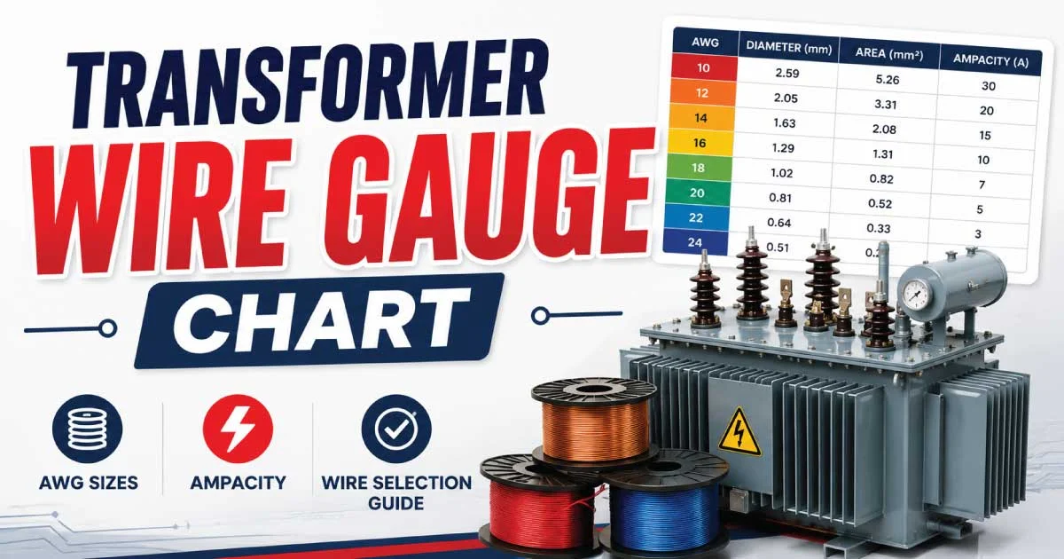
Transformer wire gauge is one of the most important factors in transformer design, performance, and safety. Selecting the correct wire size ensures efficient power transfer, minimizes energy losses, prevents overheating, and increases transformer lifespan. Whether you are designing, repairing, or studying transformers, understanding wire gauge charts helps make informed electrical decisions while maintaining compliance with safety standards.
What Is a Transformer Wire Gauge Chart?
A transformer wire gauge chart is a reference table that helps determine the appropriate wire diameter based on the transformer’s current-carrying capacity. The chart typically includes American Wire Gauge (AWG), wire diameter, cross-sectional area, and maximum current ratings. Electricians and engineers rely on these charts to select conductors that provide optimal electrical performance while avoiding excessive voltage drop and heat generation.
Why Wire Gauge Selection Is Important
Choosing the correct wire gauge directly impacts transformer efficiency and reliability. Undersized wires generate excessive heat and may fail under heavy loads, while oversized wires increase material costs without providing significant benefits. Proper wire selection balances electrical conductivity, thermal performance, mechanical strength, and cost, ensuring the transformer operates safely under expected load conditions for many years.
Key Factors Affecting Transformer Wire Gauge Selection
Several factors determine the appropriate transformer wire gauge. Each should be evaluated carefully before selecting conductor size.
- Current carrying capacity
- Voltage rating
- Transformer power rating
- Operating temperature
- Cooling method
- Winding configuration
- Copper or aluminum conductor
- Safety standards and regulations
Considering all these elements helps engineers design transformers that deliver maximum efficiency with minimal energy loss.
Understanding American Wire Gauge (AWG)
The American Wire Gauge system is a standardized method for measuring wire diameter in North America. Smaller AWG numbers indicate thicker wires capable of carrying higher currents, while larger numbers represent thinner conductors used for lighter electrical loads. The AWG system simplifies wire selection and ensures consistency across electrical manufacturing, installation, and maintenance projects worldwide.
How AWG Numbers Work
Many beginners find AWG numbering confusing because the numbers decrease as wire diameter increases. For example, 8 AWG is thicker than 12 AWG. Larger conductors offer lower electrical resistance, allowing higher current flow with reduced heat generation. Understanding this numbering system is essential for interpreting transformer wire gauge charts accurately and avoiding costly wiring mistakes.
Common Transformer Wire Materials
Transformer windings are primarily manufactured using copper or aluminum conductors. Each material offers unique advantages depending on the intended application, operating environment, and budget.
Copper Advantages
- Excellent electrical conductivity
- High mechanical strength
- Better thermal performance
- Smaller winding size
- Longer operational lifespan
Aluminum Advantages
- Lower material cost
- Lightweight construction
- Easier handling
- Suitable for large transformers
- Good corrosion resistance
Relationship Between Wire Diameter and Current Capacity
Wire diameter directly influences how much electrical current a conductor can safely carry. Thicker wires have lower electrical resistance, reducing heat buildup during operation. Thin wires experience greater resistance, limiting current capacity and increasing energy losses. Transformer designers carefully calculate conductor size to ensure reliable operation under full-load and overload conditions without damaging insulation.
Transformer Current Calculation Basics
Before selecting wire gauge, engineers calculate transformer current using standard electrical formulas. Accurate current calculations ensure the conductor can safely handle the expected electrical load throughout the transformer’s operating life.
For single-phase transformers:
Current (I) = Power (VA) ÷ Voltage (V)
For three-phase transformers:
Current (I) = VA ÷ (√3 × Voltage)
These calculations provide the foundation for selecting the proper conductor size.
Standard Transformer Wire Gauge Chart
The following chart provides a general reference for copper conductors under typical operating conditions. Actual ratings may vary depending on insulation type, installation method, and temperature.
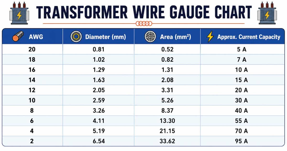
| AWG | Diameter (mm) | Area (mm²) | Approx. Current Capacity |
|---|---|---|---|
| 20 | 0.81 | 0.52 | 5 A |
| 18 | 1.02 | 0.82 | 7 A |
| 16 | 1.29 | 1.31 | 10 A |
| 14 | 1.63 | 2.08 | 15 A |
| 12 | 2.05 | 3.31 | 20 A |
| 10 | 2.59 | 5.26 | 30 A |
| 8 | 3.26 | 8.37 | 40 A |
| 6 | 4.11 | 13.30 | 55 A |
| 4 | 5.19 | 21.15 | 70 A |
| 2 | 6.54 | 33.62 | 95 A |
Transformer wire gauge chart pdf
Primary and Secondary Winding Wire Selection
Transformer primary and secondary windings often require different wire gauges because they carry different current levels. The primary winding generally operates at higher voltage and lower current, allowing thinner wire. The secondary winding usually carries higher current at lower voltage, requiring thicker conductors to safely handle increased electrical flow without excessive heating.
How Voltage Influences Wire Gauge
Voltage indirectly affects wire gauge through current requirements. High-voltage windings typically carry lower current, enabling smaller conductor sizes. Low-voltage windings draw higher current for the same power output, requiring larger wire gauges. Engineers balance voltage, current, insulation thickness, and available winding space to achieve efficient transformer performance and reliable long-term operation.
Importance of Current Density in Transformer Design
Current density refers to the amount of electrical current flowing through a unit area of conductor. Maintaining appropriate current density prevents overheating while maximizing transformer efficiency. Excessive current density shortens insulation life, whereas very low current density results in unnecessarily large transformers with increased manufacturing costs and reduced economic efficiency.
Temperature Rise and Wire Gauge
Heat is one of the biggest enemies of transformer insulation. Choosing the correct wire gauge helps minimize resistive heating and keeps operating temperatures within acceptable limits. Proper conductor sizing improves transformer reliability, reduces maintenance requirements, and extends insulation life. Designers also consider cooling methods such as natural air, oil immersion, or forced-air systems when selecting wire size.
Resistance and Voltage Drop Considerations
Electrical resistance increases as wire diameter decreases. Higher resistance causes voltage drop and energy loss in transformer windings. Larger conductors minimize resistance, improving voltage regulation and overall efficiency. Transformer designers calculate acceptable resistance values to maintain stable output voltage while ensuring efficient energy transfer under varying load conditions.
Copper Losses in Transformer Windings
Copper losses occur because every conductor has some electrical resistance. These losses increase with current and significantly affect transformer efficiency. Selecting an appropriate wire gauge minimizes copper losses, reduces operating temperatures, and lowers electricity consumption over the transformer’s service life.
The main factors influencing copper losses include:
- Wire resistance
- Load current
- Winding length
- Operating temperature
- Conductor material
Benefits of Using the Correct Wire Gauge
Selecting the proper transformer wire gauge offers numerous operational and economic advantages. Correct conductor sizing enhances performance while minimizing maintenance and replacement costs over time.
Some major benefits include:
- Improved electrical efficiency
- Lower operating temperatures
- Longer insulation lifespan
- Reduced power losses
- Better voltage regulation
- Increased transformer reliability
- Enhanced electrical safety
- Lower maintenance expenses
Common Mistakes When Choosing Transformer Wire Gauge
Many transformer failures result from incorrect conductor selection rather than manufacturing defects. Understanding common mistakes helps prevent costly repairs and unsafe operating conditions.
Avoid these frequent errors:
- Ignoring current calculations
- Selecting wire based only on diameter
- Overlooking temperature ratings
- Ignoring insulation class
- Neglecting voltage drop
- Using incorrect AWG references
- Failing to account for continuous loading
Advanced Transformer Wire Gauge Calculations
Selecting the correct transformer wire gauge requires more than simply checking a chart. Engineers perform electrical and thermal calculations to ensure the conductor safely carries the expected current without excessive heating. These calculations also account for insulation thickness, cooling methods, winding space, and acceptable voltage drop to achieve long-term transformer reliability.
How to Calculate Transformer Wire Size Step by Step
Calculating transformer wire size involves determining the operating current before selecting the appropriate conductor from a wire gauge chart. After calculating the current, engineers apply safety margins based on temperature rise, insulation class, and continuous operating conditions to ensure dependable performance.
Basic Calculation Process
- Determine transformer power rating (VA or kVA)
- Identify primary or secondary voltage
- Calculate full-load current
- Select conductor material
- Check allowable current capacity
- Consider temperature correction factors
- Verify available winding space
- Confirm compliance with electrical standards
Example 1: Wire Gauge for a 500 VA Transformer
Consider a 500 VA single-phase transformer operating at 120 volts. The full-load current is calculated by dividing power by voltage. The result helps identify the minimum wire gauge capable of safely carrying the load while allowing additional safety margin for continuous operation and temperature rise.
Calculation
- Power = 500 VA
- Voltage = 120 V
- Current = 500 ÷ 120 = 4.17 A
A conductor such as 20 AWG or 18 AWG may be suitable depending on insulation type, temperature rating, and design requirements.
Example 2: Wire Gauge for a 2 kVA Transformer
A 2 kVA transformer with a 240-volt secondary requires a higher current capacity than smaller transformers. Engineers calculate the current first and then select the nearest suitable conductor with adequate ampacity while considering cooling conditions and expected operating temperatures.
Calculation
- Power = 2,000 VA
- Voltage = 240 V
- Current = 2,000 ÷ 240 = 8.33 A
A 16 AWG or 14 AWG copper conductor is commonly considered depending on design specifications.
Example 3: Three-Phase Transformer Calculation
Three-phase transformers use a different current formula because electrical power is distributed across three conductors. Correct calculations ensure each winding safely carries its share of the electrical load without overheating during continuous industrial operation.
Calculation
- Transformer Rating = 15 kVA
- Voltage = 415 V
- Current = 15,000 ÷ (1.732 × 415)
- Current ≈ 20.9 A
A conductor near 12 AWG or 10 AWG may be selected depending on insulation, cooling, and installation conditions.
Copper vs Aluminum Transformer Windings
Copper and aluminum remain the two most common transformer winding materials. Although both conduct electricity effectively, their physical and electrical properties differ significantly. Material selection depends on efficiency goals, installation environment, transformer size, maintenance expectations, and overall project budget.
| Feature | Copper | Aluminum |
|---|---|---|
| Conductivity | Excellent | Good |
| Weight | Heavy | Lightweight |
| Cost | Higher | Lower |
| Mechanical Strength | High | Moderate |
| Corrosion Resistance | Very Good | Good |
| Winding Size | Smaller | Larger |
| Efficiency | Higher | Slightly Lower |
Importance of Insulation Class
Wire insulation is just as important as conductor size. High-quality insulation prevents short circuits, withstands elevated temperatures, and extends transformer life. Engineers choose insulation classes according to the maximum operating temperature expected during normal service and overload conditions.
Common insulation classes include:
- Class A – 105°C
- Class E – 120°C
- Class B – 130°C
- Class F – 155°C
- Class H – 180°C
Selecting the proper insulation class improves transformer durability and operational safety.
Temperature Correction Factors
Wire current ratings are based on standard ambient temperatures. Higher operating temperatures reduce conductor ampacity because heat cannot dissipate as efficiently. Engineers apply correction factors when transformers operate in hot climates, enclosed panels, or poorly ventilated environments to prevent insulation damage and premature conductor failure.
Continuous Load vs Intermittent Load
Transformers serving continuous loads require more conservative wire sizing than units operating only occasionally. Continuous operation generates sustained heat, making proper conductor selection essential for long-term reliability. Intermittent loads allow cooling periods, reducing thermal stress on windings and insulation materials between operating cycles.
Transformer Efficiency and Wire Gauge
Wire gauge has a direct impact on transformer efficiency because conductor resistance determines copper losses. Larger conductors reduce resistance, improve voltage regulation, and minimize heat generation. While larger wires increase manufacturing costs, they often lower long-term operating expenses through reduced energy losses.
How Wire Gauge Affects Voltage Regulation
Voltage regulation measures how much the output voltage changes from no-load to full-load conditions. Smaller conductors have greater resistance, causing larger voltage drops under heavy loads. Proper wire sizing helps maintain stable output voltage, ensuring electrical equipment receives consistent and reliable power throughout operation.
Common Wire Gauge Standards Around the World
Different countries use different conductor sizing standards. Although AWG dominates North America, many regions use metric conductor sizes measured in square millimeters. Understanding these standards helps engineers work on international transformer projects with greater accuracy.
| AWG | Approximate Metric Size (mm²) |
|---|---|
| 18 | 0.82 |
| 16 | 1.31 |
| 14 | 2.08 |
| 12 | 3.31 |
| 10 | 5.26 |
| 8 | 8.37 |
| 6 | 13.30 |
| 4 | 21.15 |
Transformer Winding Best Practices
Proper winding techniques improve transformer performance, reduce losses, and increase mechanical stability. Even correctly sized conductors may fail if winding procedures are poor or insulation is damaged during manufacturing.
Best practices include:
- Maintain consistent winding tension
- Avoid sharp conductor bends
- Protect insulation from abrasion
- Use proper layer insulation
- Ensure uniform winding distribution
- Minimize conductor crossover
- Secure winding firmly
- Inspect for insulation damage before assembly
Safety Considerations When Selecting Wire Gauge
Electrical safety should always be the highest priority during transformer design and installation. Proper conductor sizing prevents overheating, insulation failure, and electrical fires while ensuring compliance with recognized electrical standards and engineering practices.
Key safety recommendations include:
- Never exceed conductor ampacity
- Use approved insulation materials
- Follow manufacturer specifications
- Allow adequate cooling
- Verify all electrical connections
- Perform insulation resistance testing
- Inspect windings regularly
- Replace damaged conductors immediately
Signs That Transformer Wire Gauge Is Incorrect
Incorrect conductor sizing often reveals itself through excessive heating or declining transformer performance. Early identification prevents costly failures and unplanned equipment downtime.
Common warning signs include:
- Transformer overheating
- Burnt insulation smell
- Reduced efficiency
- Excessive voltage drop
- Frequent protective device tripping
- Discolored winding insulation
- Hot spots inside the transformer
- Shortened equipment lifespan
Maintenance Tips for Transformer Windings
Routine maintenance helps preserve conductor integrity and ensures transformers continue operating efficiently throughout their service life. Regular inspections detect developing issues before they become major failures requiring expensive repairs or transformer replacement.
Maintenance checklist:
- Inspect winding insulation
- Clean dust and contaminants
- Check operating temperature
- Measure insulation resistance
- Tighten electrical connections
- Monitor load current
- Verify cooling system performance
- Record maintenance history
Final Thoughts
Choosing the correct transformer wire gauge is essential for ensuring safe, efficient, and reliable transformer operation. The right conductor size allows the transformer to carry the required current without excessive heating, helping maintain consistent electrical performance under varying load conditions.
Selecting the appropriate wire gauge involves more than matching current capacity alone. Engineers must also consider factors such as voltage, winding configuration, current density, insulation type, temperature rise, and available winding space. These considerations help achieve an optimal balance between efficiency, durability, and manufacturing practicality.
A properly designed wire gauge reduces copper losses, improves voltage regulation, minimizes operating temperatures, and enhances the overall efficiency of the transformer. In contrast, using an undersized or oversized conductor can lead to energy losses, overheating, reduced performance, and unnecessary material costs.
Accurate current calculations, transformer wire gauge charts, high-quality insulation materials, and proper winding techniques all play a vital role in building dependable transformers. Following established engineering standards and best practices helps ensure long-term reliability while reducing maintenance requirements and extending equipment lifespan.
Whether designing small control transformers, residential units, or large industrial power distribution transformers, careful conductor selection remains one of the most critical aspects of transformer design. By using reliable wire gauge charts and sound engineering principles, professionals can create transformers that deliver safe, efficient, and long-lasting performance across a wide range of applications.
Also Read: Wire Size Chart: Choose the Right Wire Size Every Time