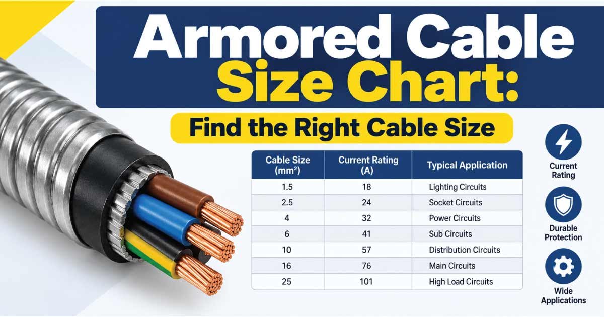
An armored cable size chart helps you compare common cable conductor sizes and understand where different armored cables may be used. Armored cables are designed to provide electrical power while adding mechanical protection through a metallic armor layer.
Common armored cable sizes range from 1.5 mm² to 630 mm², although the available sizes depend on the cable type, conductor material, voltage rating, number of cores, insulation, and manufacturer.
Choosing the correct armored cable involves more than selecting a conductor cross-sectional area. Current-carrying capacity, voltage drop, short-circuit withstand, installation method, cable length, ambient temperature, grouping, mechanical protection, and termination requirements should all be considered.
What Is Armored Cable?
An armored cable is an electrical cable containing a protective metallic layer around the insulated conductors.
The armor provides additional protection against:
- Mechanical impact
- Crushing
- Abrasion
- Installation damage
- Certain environmental conditions
- Rodent damage in appropriate applications
Depending on the cable construction, the armor may also have an electrical bonding or earthing function.
Common armored cable constructions include steel wire armored (SWA), aluminum wire armored (AWA), and steel tape armored designs.
Armored cables are widely used for power distribution, industrial equipment, underground installations, outdoor systems, commercial buildings, and other demanding applications.
Armored Cable Size Chart
The following table provides a general reference for common armored cable conductor sizes.
| Cable Size | Typical Conductor Material | Common Applications |
|---|---|---|
| 1.5 mm² | Copper / Aluminum | Small lighting and control circuits |
| 2.5 mm² | Copper / Aluminum | Small power and socket circuits |
| 4 mm² | Copper / Aluminum | Medium power circuits |
| 6 mm² | Copper / Aluminum | Larger branch circuits |
| 10 mm² | Copper / Aluminum | Small feeders and equipment |
| 16 mm² | Copper / Aluminum | Distribution and equipment |
| 25 mm² | Copper / Aluminum | Medium feeders |
| 35 mm² | Copper / Aluminum | Distribution systems |
| 50 mm² | Copper / Aluminum | Larger feeders |
| 70 mm² | Copper / Aluminum | High-current distribution |
| 95 mm² | Copper / Aluminum | Industrial feeders |
| 120 mm² | Copper / Aluminum | Large power distribution |
| 150 mm² | Copper / Aluminum | High-load feeders |
| 185 mm² | Copper / Aluminum | Industrial distribution |
| 240 mm² | Copper / Aluminum | Large power systems |
| 300 mm² | Copper / Aluminum | High-capacity feeders |
| 400 mm² | Copper / Aluminum | Heavy power distribution |
| 500 mm² | Copper / Aluminum | Large industrial systems |
| 630 mm² | Copper / Aluminum | Very high-current systems |
These are conductor cross-sectional areas, not the overall diameter of the finished armored cable.
The actual cable diameter, weight, current capacity, and construction can vary substantially between manufacturers.
Understanding Armored Cable Sizes
Armored cable size is normally expressed using the conductor’s cross-sectional area in square millimeters (mm²).
For example:
- 4 mm²
- 10 mm²
- 25 mm²
- 70 mm²
- 120 mm²
- 240 mm²
A larger mm² value generally means a larger conductor capable of carrying more current, subject to installation conditions.
However, cable size does not directly indicate:
- Overall cable diameter
- Armor thickness
- Cable weight
- Number of cores
- Insulation thickness
- Current capacity under every installation condition
For this reason, two cables with the same conductor size can have different outside dimensions.
Armored Cable Core Configurations
Armored power cables are available in different core configurations.
Common options include:
- 1-core
- 2-core
- 3-core
- 4-core
- 5-core
The correct configuration depends on the electrical system and application.
1-Core Armored Cable
Single-core armored cables are often used for high-current power transmission and specialized distribution applications.
For AC systems, the armor arrangement and magnetic effects require particular attention. Aluminum armor or other appropriate constructions may be used depending on the design.
2-Core Armored Cable
Two-core cables may be used for certain single-phase power systems where separate conductors are required for the circuit.
3-Core Armored Cable
Three-core cables are commonly used in three-phase systems where a neutral conductor is not required within the cable.
4-Core Armored Cable
Four-core armored cables can be used in three-phase systems where three phase conductors and a neutral are required.
5-Core Armored Cable
Five-core cables are commonly used where three phases, neutral, and protective earth or grounding conductors are required within the cable arrangement, depending on the system design.
SWA Cable Size Chart
Steel Wire Armored (SWA) cable is one of the most recognized types of armored power cable.
Common conductor sizes include:
| SWA Conductor Size | Typical Use |
|---|---|
| 1.5 mm² | Small power and lighting |
| 2.5 mm² | General power |
| 4 mm² | Medium circuits |
| 6 mm² | Larger branch circuits |
| 10 mm² | Small feeders |
| 16 mm² | Distribution |
| 25 mm² | Medium feeders |
| 35 mm² | Power distribution |
| 50 mm² | Larger feeders |
| 70 mm² | High-current circuits |
| 95 mm² | Industrial feeders |
| 120 mm² | Large distribution |
| 150–240 mm² | High-load systems |
| 300–630 mm² | Heavy industrial distribution |
The correct SWA cable depends on the load, installation method, voltage, cable length, and other design conditions.
Armored Cable Current Capacity
The current-carrying capacity, or ampacity, is one of the most important factors when selecting an armored cable.
However, there is no single current rating that applies to every cable size.
Ampacity depends on:
- Conductor material
- Cable insulation
- Number of cores
- Number of loaded conductors
- Installation method
- Ambient temperature
- Soil thermal conditions for buried cable
- Cable grouping
- Cable spacing
- Surrounding thermal environment
- Armor construction
- Voltage level
Therefore, an armored cable ampacity chart should always be associated with a specific cable construction and installation method.
Armored Cable Size by Approximate Current
The following table is intended only as a general planning reference.
| Approximate Design Current | Cable Sizes to Evaluate |
|---|---|
| Up to 15A | 1.5–2.5 mm² |
| Up to 25A | 2.5–4 mm² |
| Up to 35A | 4–6 mm² |
| Up to 50A | 6–10 mm² |
| Up to 70A | 10–16 mm² |
| Up to 100A | 16–25 mm² |
| Up to 125A | 25–35 mm² |
| Up to 160A | 35–50 mm² |
| Up to 200A | 50–70 mm² |
| Up to 250A | 70–95 mm² |
| Up to 315A | 95–150 mm² |
| Up to 400A | 150–240 mm² |
These ranges are not universal ampacity ratings. They are starting points for evaluation. The final cable size should be selected using the actual cable manufacturer’s data and applicable electrical requirements.
Discover More:
Copper vs Aluminum Armored Cable
Armored cables can use either copper or aluminum conductors.
Copper Armored Cable
Copper offers:
- High electrical conductivity
- Good mechanical strength
- Compact conductor dimensions
- Excellent termination characteristics
Copper cables are often preferred where space is limited or where their mechanical and electrical properties provide an advantage.
Aluminum Armored Cable
Aluminum generally offers:
- Lower conductor weight
- Lower material cost in many applications
- Larger conductor dimensions for equivalent resistance compared with copper
Aluminum can be a practical choice for larger feeders and distribution systems where weight and cost are important considerations.
The terminals and connectors must be suitable for the conductor material.
XLPE vs PVC Armored Cable
Armored cables are available with different insulation materials.
PVC Armored Cable
PVC-insulated cables are widely used for general power distribution and many conventional electrical installations.
Advantages can include:
- Cost effectiveness
- Good general insulation
- Easy availability
- Wide range of sizes
XLPE Armored Cable
XLPE (cross-linked polyethylene) insulation can provide higher conductor operating temperature capability than many PVC designs.
XLPE cables are commonly considered for:
- Higher-load applications
- Industrial power systems
- Underground distribution
- Larger feeders
- Applications requiring greater thermal performance
The actual temperature rating must always be confirmed from the cable specification.
SWA vs AWA Cable
The armor material is an important consideration.
SWA — Steel Wire Armor
SWA is commonly used for:
- Multicore power cables
- Underground power distribution
- Industrial installations
- Building power systems
Steel provides strong mechanical protection.
AWA — Aluminum Wire Armor
Aluminum Wire Armor (AWA) is commonly used in certain single-core AC cable applications.
A key reason for selecting aluminum armor in these applications is to reduce magnetic effects associated with ferromagnetic armor around a single AC conductor.
The cable design should be selected according to the electrical system and manufacturer’s specifications.
Discover More:
Armored Cable Voltage Drop
Voltage drop becomes increasingly important as cable length increases.
A cable can have sufficient current-carrying capacity while still producing excessive voltage drop over a long distance.
Voltage drop depends on:
- Cable length
- Load current
- Conductor resistance
- Conductor material
- Power factor
- Number of phases
- Cable arrangement
- Operating temperature
For long cable runs, you may need to select a larger conductor size than the minimum required for ampacity.
For three-phase systems, voltage-drop calculations commonly involve the relationship between current, cable impedance, length, and phase voltage.
Armored Cable for Underground Installation
Armored cable is often used underground because its protective armor can improve resistance to mechanical damage.
However, underground cable selection requires consideration of:
- Burial depth
- Soil thermal resistivity
- Ground temperature
- Water and moisture
- Cable grouping
- Mechanical protection
- Warning systems
- Cable spacing
- Voltage drop
Direct burial suitability should be confirmed from the cable’s construction and installation requirements.
Armor does not automatically make every cable suitable for direct burial.
Armored Cable for Outdoor Applications
Outdoor installations expose cables to environmental conditions such as:
- Sunlight
- Rain
- Moisture
- Temperature changes
- Physical impact
- Chemicals
- UV radiation
The complete cable construction should therefore be appropriate for the environment.
The outer sheath, armor, insulation, glands, joints, and terminations all contribute to the overall installation performance.
Armored Cable Glands and Terminations
Selecting the correct cable is only part of an armored cable installation.
The cable also requires appropriate glands, lugs, terminals, cleats, and accessories.
Cable gland selection can depend on:
- Cable overall diameter
- Armor type
- Number of cores
- Cable size
- Indoor or outdoor installation
- Enclosure type
- Environmental protection requirements
The gland must be compatible with the specific cable construction.
Incorrect gland selection can compromise mechanical retention, environmental sealing, and electrical continuity.
Armored Cable Size and Cable Diameter
Cable size in mm² should not be confused with overall cable diameter.
For example, a 25 mm² armored cable may have a considerably different outside diameter depending on whether it is:
- 2-core
- 3-core
- 4-core
- Copper
- Aluminum
- PVC insulated
- XLPE insulated
- SWA
- AWA
Therefore, always use the manufacturer’s dimensional data when planning:
- Cable glands
- Conduit entries
- Trunking
- Cable trays
- Ducts
- Cable cleats
- Panel entries
How to Select the Correct Armored Cable Size
1. Determine the Load
Calculate the expected design current.
For a basic single-phase load:
I = P ÷ V
For a three-phase load:
I = P ÷ (√3 × V × PF × η)
where power factor and efficiency should be included when applicable.
2. Select the Number of Cores
Determine whether the system requires:
- 1 core
- 2 cores
- 3 cores
- 4 cores
- 5 cores
3. Choose Conductor Material
Compare copper and aluminum based on electrical performance, installation requirements, weight, cost, and termination compatibility.
4. Check Ampacity
Verify that the selected cable can safely carry the design current under the actual installation conditions.
5. Check Voltage Drop
For long cable runs, calculate voltage drop and increase conductor size if necessary.
6. Check Short-Circuit Rating
The conductor and cable construction must withstand the expected fault current for the required duration.
7. Check Mechanical Requirements
Consider whether the cable needs additional protection because of impact, crushing, burial, or industrial conditions.
8. Select Compatible Accessories
Choose the correct:
- Cable glands
- Lugs
- Cleats
- Terminations
- Sealing components
Discover More:
Armored Cable Size Chart by Application
| Cable Size Range | General Application Category |
|---|---|
| 1.5–4 mm² | Lighting and small power |
| 6–16 mm² | Branch circuits and small feeders |
| 25–50 mm² | Medium power distribution |
| 70–120 mm² | Large feeders |
| 150–240 mm² | High-current distribution |
| 300–400 mm² | Heavy industrial power |
| 500–630 mm² | Very high-capacity systems |
This classification is intended to help organize cable sizes rather than establish mandatory applications.
Common Armored Cable Sizing Mistakes
Choosing Cable Size Only by Amperage
Current capacity is important, but voltage drop and installation conditions can change the required size.
Ignoring Cable Length
A long cable run can produce excessive voltage drop even when ampacity is adequate.
Ignoring Installation Conditions
Buried, enclosed, grouped, tray-mounted, and free-air cables can have different thermal performance.
Confusing Cable Size With Diameter
A 35 mm² conductor size does not mean the finished cable has a 35 mm diameter.
Using the Wrong Gland
The gland must match the cable’s armor and overall dimensions.
Ignoring Short-Circuit Performance
A cable must be capable of withstanding expected fault conditions.
Assuming All Armored Cables Are the Same
SWA, AWA, PVC, XLPE, copper, aluminum, and different core configurations can produce significantly different cable characteristics.
Frequently Asked Questions
What are the common armored cable sizes?
Common armored cable conductor sizes include 1.5, 2.5, 4, 6, 10, 16, 25, 35, 50, 70, 95, 120, 150, 185, 240, 300, 400, 500, and 630 mm². Availability varies by cable type, manufacturer, voltage rating, and conductor material.
What size armored cable do I need for 100A?
A 100A load does not automatically correspond to one specific armored cable size. Depending on conductor material, insulation, core configuration, installation method, ambient conditions, grouping, and voltage drop, different sizes may need to be evaluated.
What is the difference between SWA and AWA cable?
SWA uses steel wire armor, providing strong mechanical protection and commonly being used with multicore power cables. AWA uses aluminum wire armor and is commonly selected for certain single-core AC applications where magnetic effects from steel armor need to be avoided.
Is armored cable suitable for underground use?
Some armored cables are designed for underground installation, but not every armored cable is automatically suitable for direct burial. Burial conditions, cable construction, mechanical protection, moisture exposure, soil conditions, and applicable installation requirements must be evaluated.
Does armored cable need a larger size for long distances?
It can. A long cable run can produce greater voltage drop, so a larger conductor may be required even when the original size has sufficient current-carrying capacity. Cable length should therefore be included in the sizing calculation.
Conclusion
An armored cable size chart provides a convenient way to compare common conductor sizes from 1.5 mm² to 630 mm² and understand their general applications. However, cable selection should never be based on conductor size alone.
The correct armored cable depends on load current, conductor material, number of cores, insulation type, installation method, voltage drop, short-circuit conditions, environmental exposure, mechanical protection, and termination requirements.
For accurate cable selection, use the actual manufacturer’s cable data and verify the design against the applicable electrical requirements. Correct sizing helps provide reliable power delivery, effective protection, and safe long-term operation.