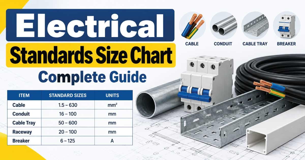
Electrical standards provide the rules and specifications used to design, install, test, operate, and maintain electrical systems. They help ensure that electrical equipment, wiring, protective devices, connectors, enclosures, and other components are suitable for their intended applications.
An Electrical Standards Size Chart can help electricians, engineers, contractors, technicians, manufacturers, and students understand common electrical sizing systems and the standards commonly associated with them.
Electrical standards can cover many different measurements, including wire size, cable dimensions, conduit size, current ratings, voltage ratings, connector dimensions, enclosure ratings, breaker ratings, and equipment classifications.
Because electrical requirements vary by country, application, equipment type, and installation method, a size chart should be treated as a planning and comparison tool rather than a replacement for the applicable electrical code or manufacturer’s specifications.
What Are Electrical Standards?
Electrical standards are technical requirements or specifications developed to promote safety, compatibility, performance, reliability, and consistency in electrical products and installations.
They can define requirements for:
- Electrical wiring
- Cable construction
- Conductor sizes
- Circuit protection
- Switchgear
- Control equipment
- Enclosures
- Plugs and sockets
- Grounding and bonding
- Testing
- Insulation
- Electrical safety
- Equipment performance
- Environmental protection
Different countries and industries may use different standards.
For this reason, the first step in electrical sizing is identifying which standard or electrical code applies to the project.
Electrical Standards Size Chart
The following chart summarizes common electrical sizing areas and the type of measurement normally used.
| Electrical Item | Common Size System | Typical Measurement | Main Purpose |
|---|---|---|---|
| Electrical wire | AWG / mm² | Conductor area | Current carrying |
| Cable | mm² / AWG | Conductor size | Power transmission |
| Conduit | Trade size / metric | Internal area | Cable routing |
| Circuit breaker | A | Current rating | Overcurrent protection |
| Fuse | A | Current rating | Circuit protection |
| Terminal | mm² / AWG | Conductor range | Wire termination |
| Cable gland | Metric / NPT | Cable diameter/thread | Cable entry |
| Busbar | mm² / dimensions | Cross-sectional area | Power distribution |
| Enclosure | mm / IP | Dimensions/protection | Equipment housing |
| Plug/socket | A/V | Current/voltage | Electrical connection |
| Transformer | VA/kVA | Power rating | Voltage conversion |
| Contactor | A/kW/HP | Load rating | Load switching |
| Relay | A/V | Contact rating | Control switching |
These are general categories. The exact requirements depend on the selected standard, product, installation, and application.
Electrical Wire Size Standards
Wire size is one of the most important electrical sizing requirements.
Two common conductor sizing systems are:
- AWG — American Wire Gauge
- mm² — square millimeters
AWG is widely used in North America and some other markets, while metric conductor sizes are common in many other regions.
A conductor’s mm² value represents its approximate cross-sectional area.
Common AWG Wire Sizes
| AWG Size | Approximate Area | General Application |
|---|---|---|
| 24 AWG | 0.205 mm² | Electronics/control |
| 22 AWG | 0.326 mm² | Control/signal |
| 20 AWG | 0.519 mm² | Control/electronics |
| 18 AWG | 0.823 mm² | Small equipment |
| 16 AWG | 1.31 mm² | Small power circuits |
| 14 AWG | 2.08 mm² | Branch circuits |
| 12 AWG | 3.31 mm² | Branch circuits |
| 10 AWG | 5.26 mm² | Higher-load circuits |
| 8 AWG | 8.37 mm² | Feeders/equipment |
| 6 AWG | 13.3 mm² | Larger feeders |
| 4 AWG | 21.2 mm² | High-current circuits |
| 2 AWG | 33.6 mm² | Feeders |
| 1/0 AWG | 53.5 mm² | Large feeders |
| 2/0 AWG | 67.4 mm² | High-current systems |
| 4/0 AWG | 107 mm² | Large electrical systems |
The actual allowable current of a conductor cannot be determined from AWG alone. It also depends on conductor material, insulation, installation method, ambient temperature, grouping, and applicable requirements.
Metric Electrical Wire Size Chart
Metric cable and wire sizes are commonly identified by conductor cross-sectional area.
| Metric Size | General Size Category | Common Application |
|---|---|---|
| 0.5 mm² | Small | Control/electronics |
| 0.75 mm² | Small | Control wiring |
| 1.0 mm² | Small | Lighting/control |
| 1.5 mm² | Small power | Lighting and small circuits |
| 2.5 mm² | Medium | General branch circuits |
| 4 mm² | Medium | Higher-load circuits |
| 6 mm² | Medium/large | Equipment circuits |
| 10 mm² | Large | Feeders/equipment |
| 16 mm² | Large | Distribution |
| 25 mm² | Large | Feeders |
| 35 mm² | Large | Power distribution |
| 50 mm² | Large | Higher-current systems |
| 70 mm² | Heavy | Industrial distribution |
| 95 mm² | Heavy | Feeders |
| 120 mm² | Heavy | Power distribution |
| 150 mm²+ | Very heavy | Large industrial systems |
These are conductor-size references, not universal ampacity values.
Electrical Cable Size Standards
Cable standards can specify:
- Conductor material
- Conductor size
- Insulation
- Number of cores
- Sheath
- Voltage rating
- Temperature rating
- Mechanical characteristics
- Fire performance
- Environmental properties
Common cable size terminology includes:
1.5 mm², 2.5 mm², 4 mm², 6 mm², 10 mm², 16 mm², 25 mm², 35 mm², 50 mm², 70 mm², 95 mm², 120 mm², 150 mm², 185 mm², 240 mm², 300 mm², 400 mm² and larger.
A cable’s conductor area does not equal its overall diameter. A multi-core cable with insulation and an outer sheath can be substantially larger than the conductor itself.
Conduit Size Standards
Conduit protects electrical conductors and provides a pathway for wiring.
Conduit may be identified using:
- Trade size
- Nominal diameter
- Metric outside diameter
- Internal diameter
Common trade sizes include:
| Trade Size | Approximate Nominal Size | Typical Use |
|---|---|---|
| 1/2 in | Small | Branch wiring |
| 3/4 in | Small/medium | Multiple conductors |
| 1 in | Medium | Larger branch circuits |
| 1-1/4 in | Medium/large | Feeders |
| 1-1/2 in | Large | Larger feeders |
| 2 in | Large | Multiple cables |
| 2-1/2 in | Large | Distribution |
| 3 in | Very large | Large feeders |
| 3-1/2 in | Very large | Industrial |
| 4 in | Very large | Large cable installations |
Conduit selection should account for conductor dimensions, fill requirements, bending space, installation method, and applicable electrical requirements.
Electrical Conduit Fill Standards
Conduit cannot normally be filled completely with conductors.
Common maximum fill percentages used in many electrical systems include:
| Number of Conductors | Common Maximum Fill Reference |
|---|---|
| 1 conductor | 53% |
| 2 conductors | 31% |
| 3 or more conductors | 40% |
The exact rule depends on the applicable code and raceway type.
The basic concept is:
Total conductor area ≤ allowable conduit fill area
Actual conductor dimensions should be used rather than relying only on nominal wire size.
Circuit Breaker Size Standards
Circuit breakers are commonly rated in amperes.
Common ratings include:
| Breaker Rating | General Application |
|---|---|
| 6 A | Small circuits |
| 10 A | Lighting/control |
| 16 A | Small branch circuits |
| 20 A | General branch circuits |
| 25 A | Dedicated equipment |
| 32 A | Higher-load circuits |
| 40 A | Equipment circuits |
| 50 A | Larger loads |
| 63 A | Distribution |
| 80 A | Higher-current systems |
| 100 A | Feeders |
| 125 A+ | Larger distribution |
Breaker sizing must be coordinated with conductor ampacity and the complete circuit design.
Other important specifications include:
- Voltage
- Number of poles
- Trip curve
- Interrupting rating
- Frequency
- Protection characteristics
Fuse Size Standards
Fuses are also rated by current and voltage.
Common fuse ratings include:
| Fuse Rating | General Application |
|---|---|
| 1 A | Control/electronic circuits |
| 2 A | Control circuits |
| 5 A | Small equipment |
| 10 A | Small electrical loads |
| 15 A | Equipment circuits |
| 20 A | General equipment |
| 30 A | Higher-current loads |
| 40 A | Equipment |
| 50 A | Larger loads |
| 63 A | Distribution |
| 100 A+ | Industrial equipment |
Fuse type is important because different fuse constructions have different operating characteristics.
Electrical Terminal Size Standards
Terminal blocks and connectors are generally sized according to the conductor they accept.
Common conductor ranges include:
| Terminal Category | Typical Conductor Size |
|---|---|
| Small | 0.5–1.5 mm² |
| Small | 1.5–2.5 mm² |
| Medium | 4–6 mm² |
| Medium | 10–16 mm² |
| Large | 25–35 mm² |
| Heavy duty | 50–70 mm² |
| Industrial | 95–120 mm² |
| Heavy industrial | 150 mm²+ |
Always verify the actual conductor range, voltage rating, current rating, and terminal construction.
Discover More:
Cable Gland Size Standards
Cable glands can use different thread standards and sizing systems.
Common thread families include:
- Metric
- NPT
- PG
- Other application-specific thread systems
Metric sizes may include:
M16, M20, M25, M32, M40, M50, M63, M75, M90 and M100.
However, selecting a cable gland requires more than matching the thread.
You should check:
- Cable outside diameter
- Gland clamping range
- Thread type
- Thread size
- Cable construction
- Armor requirements
- IP rating
- Material compatibility
Electrical Enclosure Standards and Sizes
Electrical enclosures protect electrical equipment against physical and environmental hazards.
Common enclosure measurements include:
- Width
- Height
- Depth
- Wall thickness
- Mounting dimensions
- Cable-entry dimensions
Environmental protection is often expressed through an IP rating.
Examples include:
- IP20
- IP40
- IP54
- IP55
- IP65
- IP66
- IP67
- IP68
The appropriate rating depends on the installation environment.
For example, equipment exposed to water or outdoor conditions generally requires more environmental protection than equipment installed in a clean indoor electrical room.
Electrical Plug and Socket Standards
Plugs and sockets differ significantly between countries and applications.
Important specifications include:
- Voltage
- Current
- Number of contacts
- Pin configuration
- Frequency
- Grounding arrangement
- Physical dimensions
- Environmental protection
Common current ratings can include:
6 A, 10 A, 13 A, 15 A, 16 A, 20 A, 30 A, 32 A, 50 A, 63 A and higher.
A plug and socket must be physically and electrically compatible. Never modify a connection simply to make incompatible equipment fit.
Discover More:
Electrical Component IP Rating Chart
The IP rating describes protection provided by an enclosure against specified ingress conditions.
| IP Rating | General Protection Concept |
|---|---|
| IP20 | Basic finger/contact protection |
| IP44 | Protection against solid objects and splashing |
| IP54 | Dust protection and water splashing |
| IP55 | Dust protection and water jets |
| IP65 | Dust-tight and water jets |
| IP66 | Dust-tight and stronger water jets |
| IP67 | Dust-tight and temporary immersion |
| IP68 | Dust-tight and suitable for specified continuous immersion conditions |
The exact test conditions depend on the applicable standard and product specification.
Electrical Voltage Classifications
Electrical systems can be classified according to voltage ranges.
The terminology varies between standards and jurisdictions, so there is no single universal classification table for every application.
In general, electrical systems may be discussed as:
- Extra-low voltage
- Low voltage
- Medium voltage
- High voltage
- Very high voltage
The actual voltage boundaries depend on the applicable standard.
This is particularly important when working with industrial distribution systems because insulation, clearances, protective equipment, switching devices, and installation practices can change substantially with voltage.
Electrical Standards for Components
Different electrical products can be covered by different standards or technical specifications.
Examples of areas commonly standardized include:
| Component | Standardized Characteristics |
|---|---|
| Wire | Conductor, insulation, dimensions |
| Cable | Construction, voltage, performance |
| Breaker | Protection and interrupting characteristics |
| Fuse | Current, voltage, operating characteristics |
| Switchgear | Switching and protection |
| Enclosure | Dimensions and ingress protection |
| Terminal | Conductor capacity and electrical rating |
| Connector | Mechanical/electrical compatibility |
| Transformer | Voltage and power characteristics |
| Motor | Frame, power, performance |
| Plug/socket | Pin arrangement and electrical ratings |
A product may comply with one or more standards depending on its market and intended use.
Why Electrical Standards Matter
Electrical standards provide several important benefits.
Safety
Standards help establish minimum requirements for insulation, protection, grounding, clearances, and equipment construction.
Compatibility
Standardized dimensions and electrical ratings make it easier to connect compatible equipment.
Reliability
Products designed and tested according to appropriate standards can provide predictable performance under specified conditions.
Consistency
Standardized wire sizes, component ratings, connection methods, and testing procedures make electrical work more consistent.
Maintenance
Standardized components are often easier to identify, replace, and maintain.
Discover More:
How to Choose the Correct Electrical Size
Use the following process when selecting an electrical component.
1. Identify the Application
Determine whether the component is being used for:
- Residential
- Commercial
- Industrial
- Automotive
- Control
- Distribution
- Outdoor
- Underground
- Specialized equipment
2. Identify the Applicable Standard
Determine which electrical code, product standard, or technical requirement applies.
This should be established before selecting the component.
3. Determine Electrical Requirements
Check:
- Voltage
- Current
- Frequency
- Load type
- Number of phases
- Fault conditions
4. Determine Physical Requirements
Check:
- Component dimensions
- Mounting arrangement
- Conductor size
- Cable diameter
- Enclosure space
- Terminal dimensions
5. Check Environmental Conditions
Consider:
- Temperature
- Moisture
- Dust
- Chemicals
- Vibration
- Outdoor exposure
- Corrosion
6. Verify Product Information
Use the manufacturer’s technical data to confirm that the selected component meets the required electrical and physical specifications.
Electrical Standards vs Electrical Codes
Electrical standards and electrical codes are related but are not necessarily the same thing.
A standard generally provides technical requirements, specifications, test methods, dimensions, or performance criteria.
An electrical code provides rules governing electrical installations and safety.
A product can be manufactured according to a particular standard, while the installation must also comply with the electrical code applicable to the project.
This distinction is important when selecting electrical equipment.
Common Electrical Standards Sizing Mistakes
Avoid these common mistakes:
- Assuming one standard applies worldwide
- Using an AWG chart when metric sizing is required
- Confusing conductor area with cable outside diameter
- Selecting conduit based only on nominal size
- Ignoring conduit fill
- Selecting a breaker without checking the conductor
- Choosing cable glands only by thread size
- Ignoring IP requirements
- Confusing physical size with electrical rating
- Assuming similar-looking components are interchangeable
- Ignoring voltage and frequency
- Using outdated or inappropriate technical information
- Failing to verify manufacturer specifications
The correct approach is to identify the project location, application, applicable requirements, and product specification before making the final selection.
Quick Electrical Standards Size Reference
| Sizing Area | Common Measurement |
|---|---|
| Wire | AWG or mm² |
| Cable | mm² and overall diameter |
| Conduit | Trade size or metric diameter |
| Breaker | Amperes |
| Fuse | Amperes |
| Contactor | Current/load rating |
| Relay | Coil and contact rating |
| Terminal | AWG or mm² |
| Cable gland | Cable diameter/thread |
| Busbar | Width × thickness |
| Enclosure | Width × height × depth |
| Plug/socket | Current and voltage |
| Transformer | VA/kVA |
| Motor | kW/HP and frame size |
| Enclosure protection | IP rating |
FAQs About Electrical Standards Size Chart
What is an electrical standards size chart?
An electrical standards size chart is a reference guide that organizes common electrical measurements and ratings, such as wire sizes, cable sizes, conduit dimensions, breaker ratings, terminal sizes, cable glands, enclosure ratings, and other component specifications.
Why are electrical standards important?
Electrical standards help establish consistent requirements for safety, performance, dimensions, testing, construction, and compatibility. They allow manufacturers and electrical professionals to work from recognized technical requirements rather than relying on arbitrary component sizes or installation practices.
Are electrical standards the same in every country?
No. Different countries and regions can use different electrical codes, product standards, sizing systems, and installation requirements. Some standards are internationally recognized, while others are regional or industry-specific. Always identify the requirements applicable to the specific project.
What are the most common electrical wire sizing systems?
The two widely encountered systems are AWG and metric square millimeters (mm²). AWG is common in North America, while metric conductor sizing is widely used internationally. Conversion between the systems is approximate because the standardized sizes do not always correspond exactly.
Does a larger wire always carry more current?
Not necessarily under every installation condition. A larger conductor generally has greater current-carrying capability, but allowable ampacity also depends on conductor material, insulation, ambient temperature, installation method, grouping, and applicable electrical requirements.
How do I select the correct conduit size?
Determine the number and actual outside dimensions of the conductors, calculate the allowable conduit fill, and select a conduit that provides adequate space. Also consider bending requirements, installation conditions, conductor type, and applicable electrical rules.
What does an IP rating mean?
An IP rating identifies the degree of protection provided by an enclosure against specified ingress of solid objects and water. The two digits represent different protection characteristics. The required IP rating depends on the environment where the equipment will be installed.
What is the difference between an electrical standard and an electrical code?
A standard generally establishes technical specifications, performance requirements, dimensions, or test methods. An electrical code establishes installation and safety requirements. Both may be relevant to an electrical project, but they serve different purposes.
Conclusion
An Electrical Standards Size Chart is a useful reference for understanding the different sizing systems used throughout electrical engineering and installation work. Wire and cable may be identified by AWG or mm², conduit by trade or metric size, breakers and fuses by current rating, cable glands by cable diameter and thread, and enclosures by physical dimensions and IP rating.
However, electrical sizing cannot be based on a single chart alone. The correct selection depends on the applicable electrical standard, local code, system voltage, load current, conductor characteristics, installation method, environmental conditions, and manufacturer requirements.
For reliable electrical work, use size charts for initial comparison and planning, then verify the exact requirements using the applicable code, standard, and product documentation. This approach helps improve safety, compatibility, reliability, and long-term electrical system performance.