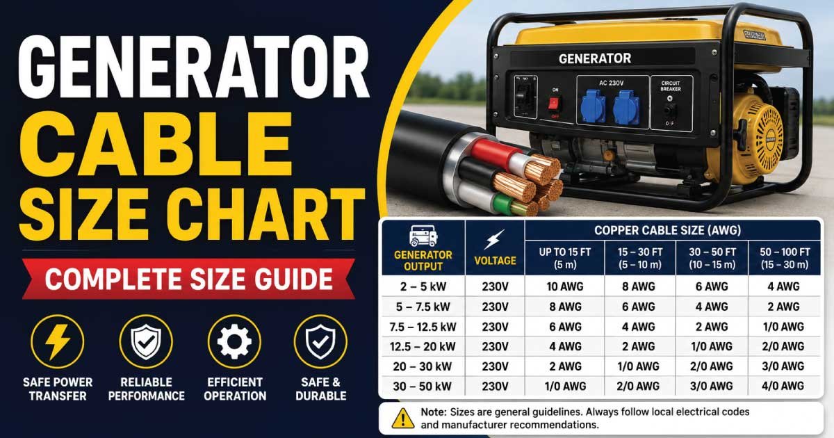
A generator cable is responsible for carrying electrical power safely from a generator to a transfer switch, distribution panel, electrical load, or connected equipment. Selecting the correct cable size is essential because an undersized cable can overheat, cause excessive voltage drop, reduce generator performance, and create a serious safety hazard.
Generator cable sizing depends on several factors, including generator output, voltage, phase, current, cable length, conductor material, installation method, ambient temperature, insulation rating, and allowable voltage drop.
A larger generator does not automatically mean that one specific cable size will always be correct. The cable must be selected according to the actual current produced by the generator and the conditions under which the cable will operate.
This guide explains common generator cable sizes, ampacity, single-phase and three-phase calculations, copper versus aluminum cables, voltage drop, cable length, installation methods, and how to select the correct cable for a generator.
What Is Generator Cable?
Generator cable is an electrical power cable used to transfer electricity generated by a generator to another part of an electrical system.
Depending on the installation, it may connect:
- Generator to transfer switch.
- Generator to distribution panel.
- Generator to temporary power distribution.
- Generator to industrial machinery.
- Generator to building electrical system.
- Portable generator to equipment.
Generator cables can be manufactured using copper or aluminum conductors, with insulation designed for particular voltage, temperature, flexibility, and environmental requirements.
The correct cable must be capable of carrying the generator’s maximum expected current without exceeding its allowable temperature.
Why Generator Cable Size Matters
Correct cable sizing is important for electrical safety and system performance.
An undersized cable can cause:
- Excessive heating.
- Voltage drop.
- Insulation damage.
- Reduced equipment performance.
- Generator overload conditions.
- Increased electrical losses.
- Potential fire hazards.
An oversized cable is generally electrically safer from an ampacity perspective, but it can increase:
- Material cost.
- Installation difficulty.
- Conduit size.
- Lug and termination requirements.
- Cable weight.
The objective is to select a cable that is properly rated for the generator and installation conditions.
Generator Cable Size Chart
The following table provides a general reference for common generator cable sizes and approximate current capacities. Actual ampacity can vary according to conductor material, insulation temperature rating, installation method, ambient temperature, number of loaded conductors, and applicable electrical codes.
| Generator Cable Size | Approx. Copper Ampacity* | Common Generator Application |
|---|---|---|
| 1.5 mm² | 10–16 A | Small portable generators |
| 2.5 mm² | 16–25 A | Small generators and light loads |
| 4 mm² | 25–32 A | Small to medium generators |
| 6 mm² | 32–40 A | Medium generator circuits |
| 10 mm² | 45–60 A | Medium-power generators |
| 16 mm² | 60–80 A | Larger generator connections |
| 25 mm² | 80–105 A | High-current generator systems |
| 35 mm² | 100–130 A | Large generator feeders |
| 50 mm² | 125–160 A | Heavy-duty generator connections |
| 70 mm² | 160–200 A | Large commercial generators |
| 95 mm² | 190–245 A | High-capacity generator feeders |
| 120 mm² | 220–285 A | Large industrial systems |
| 150 mm² | 250–325 A | Heavy industrial generators |
| 185 mm² | 285–365 A | Very large generator feeders |
| 240 mm² | 330–425 A | High-capacity industrial systems |
*Approximate reference values only. Do not use this table as a substitute for the applicable electrical code or manufacturer’s cable ampacity tables.
Generator Cable Size by Generator Capacity
Generator output is commonly specified in watts (W), kilowatts (kW), or kilovolt-amperes (kVA).
The required cable size depends on the generator’s current rather than its kW rating alone.
Some common generator capacities include:
- 2 kW.
- 3 kW.
- 5 kW.
- 7.5 kW.
- 10 kW.
- 15 kW.
- 20 kW.
- 30 kW.
- 50 kW.
- 75 kW.
- 100 kW.
- 150 kW.
- 250 kW.
- 500 kW and larger.
The voltage and phase configuration can make a major difference in the current required.
How to Calculate Generator Current
For a single-phase generator, current can be estimated using:
I = P ÷ V
Where:
- I = current in amperes.
- P = power in watts.
- V = voltage.
For example, a 5,000 W generator operating at 230 V:
I = 5,000 ÷ 230
I ≈ 21.7 A
The cable should not simply be selected based on this number alone. Continuous loading, power factor, temperature, installation method, voltage drop, and applicable electrical requirements must also be considered.
Three-Phase Generator Cable Calculation
For a three-phase generator, the current can be estimated using:
I = P ÷ (√3 × V × PF)
Where:
- I = current.
- P = real power in watts.
- V = line-to-line voltage.
- PF = power factor.
For a generator rated in kVA, the calculation can be simplified to:
I = kVA × 1000 ÷ (√3 × V)
For example, a 100 kVA, 400 V three-phase generator:
I = 100,000 ÷ (1.732 × 400)
I ≈ 144 A
The final cable selection must then account for ampacity, installation conditions, voltage drop, and applicable electrical requirements.
Generator Cable Size for 5 kW Generator
A 5 kW generator operating at approximately 230 V single phase produces roughly:
5,000 ÷ 230 ≈ 21.7 A
Depending on the installation conditions, a 4 mm² or 6 mm² copper cable may be considered.
For longer cable runs, 6 mm² or a larger conductor may be required to reduce voltage drop.
The generator’s rated output, maximum current, protection device, and cable installation method should be checked before selecting the final size.
Generator Cable Size for 10 kW Generator
A 10 kW generator at 230 V single phase produces approximately:
10,000 ÷ 230 ≈ 43.5 A
A cable in the range of 10 mm² copper may be appropriate in some installations, but the actual selection depends on installation conditions and applicable ampacity requirements.
If the generator uses three-phase output, the current per phase will be substantially different.
Generator Cable Size for 20 kW Generator
For a 20 kW single-phase generator at 230 V:
20,000 ÷ 230 ≈ 87 A
This type of generator may require a substantially larger cable, potentially around 25 mm² copper or larger, depending on the installation.
For a three-phase generator, the current is lower per phase for the same total power at the same voltage, so the cable arrangement will be different.
Generator Cable Size for 30 kW Generator
A 30 kW generator can produce a significant amount of current.
For a three-phase 400 V system with an assumed power factor of 0.8:
I = 30,000 ÷ (1.732 × 400 × 0.8)
I ≈ 54 A
A cable around 16 mm² copper may be considered in some installation conditions, but the final selection requires a proper ampacity and voltage-drop calculation.
Generator Cable Size for 50 kW Generator
For a 50 kW, three-phase, 400 V generator at a power factor of 0.8:
I ≈ 90 A
Depending on installation conditions, 25 mm² or 35 mm² copper cable may be considered.
The actual cable size should be selected after checking:
- Generator rated current.
- Cable ampacity.
- Cable length.
- Installation method.
- Ambient temperature.
- Voltage drop.
- Protective-device rating.
Generator Cable Size for 100 kW Generator
A 100 kW three-phase generator at 400 V and 0.8 power factor produces approximately:
I ≈ 180 A
A cable arrangement such as 70 mm² copper may be considered depending on the installation method and required ampacity.
For large generators, multiple parallel conductors may also be used when permitted and properly designed.
Also Read: Battery Cable Size Chart: Correct AWG Cable Guide
Generator Cable Size for 250 kW Generator
A 250 kW three-phase generator at 400 V and 0.8 power factor produces approximately:
I ≈ 451 A
A single conductor of one standard size may not be practical. Large generator installations often use multiple parallel cables per phase.
For example, the design could use several appropriately sized conductors in parallel, provided the installation complies with applicable electrical requirements.
Copper vs Aluminum Generator Cable
Both copper and aluminum conductors can be used for generator power connections when the equipment and installation are designed for them.
Copper Cable
Advantages include:
- Excellent electrical conductivity.
- Smaller conductor size for the same ampacity in many applications.
- Good mechanical strength.
- Reliable terminations.
- Common availability.
Disadvantages include:
- Higher material cost.
- Greater weight per unit length compared with aluminum.
Aluminum Cable
Advantages include:
- Lower weight.
- Lower material cost.
- Useful for large feeders.
- Available in large conductor sizes.
Disadvantages include:
- Larger conductor size may be required.
- Terminations require proper compatibility.
- Installation requires attention to manufacturer requirements.
The cable material should be compatible with the generator terminals, breakers, lugs, and other equipment.
Generator Cable Size and Voltage Drop
Voltage drop becomes increasingly important as the cable gets longer.
For example, a generator located far away from a distribution panel may experience more voltage loss than one located only a few meters away.
Excessive voltage drop can cause:
- Motors to start poorly.
- Lights to dim.
- Equipment to malfunction.
- Increased current in certain loads.
- Reduced electrical efficiency.
For long generator cable runs, increasing the conductor size can help reduce voltage drop.
Generator Cable Length
Cable length is an important factor in generator installations.
A short connection may work effectively with a smaller conductor, while the same load over a long distance may require a larger cable.
When calculating cable size, consider:
- One-way cable length.
- Circuit configuration.
- Current.
- Conductor resistance.
- Operating voltage.
- Power factor.
- Allowable voltage drop.
For three-phase systems, the voltage-drop calculation differs from single-phase circuits.
Generator Cable Size for 230V
230V generator systems are common in many residential and small commercial applications.
Typical cable sizes may include:
- 2.5 mm².
- 4 mm².
- 6 mm².
- 10 mm².
- 16 mm².
- 25 mm².
- Larger sizes for higher-current generators.
The appropriate size depends on generator output and installation conditions.
For a 230V system, current can become relatively high as generator power increases, making conductor sizing particularly important.
Generator Cable Size for 400V Three Phase
Three-phase 400V systems are common for commercial and industrial generators.
Because power is distributed across three phases, the current required for a given power output is lower than for an equivalent single-phase load at the same voltage.
Common cable sizes may include:
- 6 mm².
- 10 mm².
- 16 mm².
- 25 mm².
- 35 mm².
- 50 mm².
- 70 mm².
- 95 mm².
- 120 mm² and larger.
Large generators may use multiple parallel cables.
Also Read: Electrical Wire Size Chart: Choose the Right Wire Gauge
Generator Cable for Portable Generators
Portable generators often use flexible cables because they may be moved or temporarily connected to equipment.
Important characteristics include:
- Flexibility.
- Mechanical durability.
- Correct current rating.
- Suitable insulation.
- Outdoor suitability where required.
- Resistance to abrasion.
- Correct connector rating.
Portable generator cables should never be undersized simply because the cable run is temporary.
Temporary installations can still carry significant electrical current and require proper protection.
Generator Cable for Standby Generators
Standby generators are commonly connected to a building through a transfer switch.
A typical arrangement may be:
Generator → Generator Feeder Cable → Transfer Switch → Distribution Panel → Loads
The cable size must be coordinated with the generator output, transfer switch rating, circuit protection, and installation method.
The neutral and grounding arrangement must also follow the generator and electrical system design.
Generator Cable for Industrial Generators
Industrial generators can produce hundreds or thousands of amperes.
Large systems may use:
- Large single-core cables.
- Multicore cables.
- Parallel conductors.
- Busbars.
- Cable trays.
- Specialized generator connectors.
Industrial generator cable sizing requires careful engineering because short-circuit current, voltage drop, heat dissipation, mechanical forces, and termination requirements become increasingly important at high power levels.
Generator Cable Installation Methods
Cable ampacity depends heavily on how the cable is installed.
Common methods include:
- Free air.
- Conduit.
- Cable tray.
- Direct burial.
- Underground duct.
- Flexible temporary cable.
- Enclosed electrical equipment.
A cable that can carry a particular current in free air may have a lower allowable ampacity when installed in a confined conduit with several other loaded conductors.
Always use ampacity values appropriate for the actual installation method.
Generator Cable Temperature Rating
Cable insulation is designed for specific operating temperatures.
Common insulation temperature ratings include:
- 60°C.
- 75°C.
- 90°C.
However, the usable ampacity may be limited by the equipment termination rating or other installation requirements.
Temperature is particularly important for generator cables because large currents can produce significant heat.
Generator Cable Ampacity
Ampacity is the maximum current a conductor can carry continuously under specified conditions without exceeding its temperature rating.
Ampacity depends on:
- Conductor material.
- Conductor size.
- Insulation.
- Ambient temperature.
- Number of current-carrying conductors.
- Installation method.
- Raceway configuration.
- Cable spacing.
Never select a generator cable based solely on a generic ampacity chart.
Generator Cable and Circuit Breaker Size
The generator cable and protective device should be properly coordinated.
For example:
Generator → Main Breaker → Generator Cable → Transfer Switch
The breaker should provide appropriate protection for the conductor and generator system.
The cable should not be selected merely because its ampacity happens to be close to the generator’s rated current.
Generator protection may also involve:
- Overcurrent protection.
- Short-circuit protection.
- Ground-fault protection.
- Generator-specific protective functions.
Generator Cable Terminations
Cable termination is just as important as cable sizing.
Large generator cables may require:
- Compression lugs.
- Mechanical lugs.
- Crimp terminals.
- Cable glands.
- Busbar connections.
The termination must be rated for:
- Conductor material.
- Conductor size.
- Current.
- Voltage.
- Temperature.
- Equipment connection.
Improperly tightened or incompatible terminals can create significant heat and resistance.
Also Read: Welding Cable Size Chart: Choose the Right Cable Size
Generator Cable Flexible vs Rigid
Generator connections may require flexibility, especially when connecting portable generators or equipment that experiences vibration.
Flexible generator cables can help with:
- Equipment movement.
- Vibration.
- Temporary connections.
- Easier routing.
Fixed generator feeders may use rigid cable installations such as conduit or cable tray.
The cable construction should match the installation environment.
How to Choose the Correct Generator Cable Size
Follow these steps:
- Identify the generator’s rated output.
- Determine whether the generator is single phase or three phase.
- Determine the operating voltage.
- Calculate the full-load current.
- Identify the conductor material.
- Select the cable insulation type.
- Determine the installation method.
- Check the cable ampacity.
- Calculate voltage drop.
- Consider ambient temperature.
- Apply conductor derating factors where required.
- Check the generator and transfer-switch terminals.
- Verify the protective-device rating.
- Select suitable cable glands, lugs, and connectors.
- Confirm compliance with applicable electrical standards.
This process produces a much more reliable result than choosing a cable from generator kW alone.
Common Generator Cable Sizing Mistakes
Choosing Cable Size Only From Generator kW
The generator’s kW rating does not tell you the exact cable size without knowing voltage, phase, power factor, and installation conditions.
Ignoring Cable Length
Long cable runs can create significant voltage drop.
Ignoring Installation Method
Cable ampacity can change depending on whether the cable is installed in conduit, tray, underground duct, or free air.
Using an Undersized Cable
An undersized cable can overheat and create serious safety risks.
Ignoring Temperature
High ambient temperatures can reduce allowable cable ampacity.
Mixing Copper and Aluminum Incorrectly
Terminations must be specifically compatible with the conductor material.
Ignoring Generator Starting Loads
Motors, pumps, compressors, and other equipment can have high starting currents.
Using Incorrect Terminations
A correctly sized cable can still become dangerous if its lugs or terminals are improperly selected or installed.
Generator Cable Size Quick Reference
| Generator Output | Typical Cable Consideration |
|---|---|
| 2–3 kW | 2.5–4 mm² |
| 5 kW | 4–6 mm² |
| 7.5 kW | 6–10 mm² |
| 10 kW | 10 mm² |
| 15 kW | 10–16 mm² |
| 20 kW | 16–25 mm² |
| 30 kW | 16–25 mm² |
| 50 kW | 25–35 mm² |
| 75 kW | 35–50 mm² |
| 100 kW | 50–70 mm² |
| 150 kW | 70–95 mm² |
| 250 kW | 120–185 mm² or parallel cables |
These are general planning ranges, not final cable-selection recommendations. The actual cable size can be significantly different depending on voltage, phase, cable length, conductor material, installation method, temperature, and allowable voltage drop.
Frequently Asked Questions
What size cable do I need for a generator?
The correct generator cable size depends on generator power, voltage, phase, current, cable length, conductor material, installation method, and allowable voltage drop. A 5 kW generator may require a much smaller cable than a 50 kW generator, but the exact size should be calculated rather than estimated from kW alone.
What cable size is suitable for a 5 kW generator?
For a 5 kW, 230V single-phase generator, the calculated current is approximately 21.7A. Depending on installation conditions, 4 mm² or 6 mm² copper cable may be considered. Longer runs can require a larger conductor to control voltage drop.
What cable size is suitable for a 10 kW generator?
A 10 kW generator at 230V single phase produces approximately 43.5A. Depending on installation conditions, a cable around 10 mm² copper may be suitable in some installations. The final size should be checked against ampacity, voltage drop, temperature, and protective-device requirements.
Does generator cable size depend on distance?
Yes. Cable length affects voltage drop. A longer generator cable can lose more voltage than a short cable carrying the same current. If the voltage drop becomes excessive, a larger conductor may be required. Always consider the complete cable route when selecting the conductor size.
Is copper or aluminum better for generator cable?
Copper offers higher conductivity and can provide a smaller conductor size for a given current in many applications. Aluminum is lighter and often less expensive, especially for large feeders. Both can be suitable when the cable, lugs, terminals, and equipment are specifically rated for the conductor material.
Can I use an extension cable for a generator?
A properly rated heavy-duty generator extension cable can be used for suitable portable-generator applications. It must have adequate current capacity, insulation, flexibility, and environmental rating. Long extension cables may also require larger conductors to reduce voltage drop.
How do I calculate generator cable size?
First calculate the generator’s full-load current using its power and voltage. Then select a conductor with adequate ampacity while considering installation method, ambient temperature, conductor grouping, voltage drop, cable length, and applicable electrical requirements. The final cable should also be compatible with the generator terminals and protective devices.
Final Thoughts
Selecting the correct generator cable size is essential for safe and efficient power transmission. The most important factors are generator output, operating voltage, phase, current, cable length, conductor material, installation method, temperature, and voltage drop.
For smaller generators, cable sizes such as 2.5 mm², 4 mm², 6 mm², and 10 mm² may commonly be encountered. Medium and large generators can require 16 mm², 25 mm², 35 mm², 50 mm², 70 mm², 95 mm², 120 mm², or larger conductors.
Large industrial generators may require multiple cables connected in parallel rather than one extremely large conductor.
Remember that a generator’s kW rating alone is not enough to determine cable size. A 10 kW generator at 230V single phase has a very different current requirement from a 10 kW generator at 400V three phase. Cable length can also change the final selection because of voltage drop.
For a professional installation, always verify the generator manufacturer’s specifications, cable ampacity tables, protective-device requirements, termination ratings, and applicable electrical codes before installation.